
EMAIL:
lh@longhuamachine.com
TELL/whatsapp:
+8619305527239  English English
Views: 0 Author: Site Editor Publish Time: 2026-08-26 Origin: Site


Energy consumption and molten metal transfer logistics drive operational costs in nonferrous die casting facilities. Poor spatial planning and inefficient placement of a natural gas melting furnace lead to excessive thermal loss during transfer, bottlenecked production cycles, and heightened workplace safety hazards. Facility managers must address these spatial challenges to maintain profitable operations. This guide provides a technical evaluation framework for process engineers and plant managers to design, select, and implement an optimized furnace layout. We explore strategies that balance thermal efficiency, regulatory compliance, and operator safety. Proper planning prevents costly retrofits and ensures smooth metal flow across the production floor.
Layout Dictates Energy Use: Minimizing the transfer distance between the melting furnace and holding crucibles reduces molten metal temperature drops, lowering the required tap temperature and reducing overall gas consumption.
Centralized vs. Decentralized Trade-offs: The choice between a single high-capacity central melting hub and multiple point-of-use furnaces fundamentally alters facility footprint, material flow, and exhaust infrastructure.
Gas vs. Electric Footprints: Natural gas systems require specific spatial allowances for combustion air, exhaust flues, and gas trains, which differ significantly from the electrical panel and water-cooling footprints of induction alternatives.
Compliance is Structural: Industrial gas furnaces require strict adherence to safety standards (e.g., FM, CFA, NFPA), dictating specific clearances for high-pressure gas regulators, combustion air blowers, and emergency shut-off routing.
Maintenance Access Equals Uptime: Designing layouts with adequate clearance for refractory relining, burner tuning, lid swing arcs, and dross removal is critical for long-term equipment viability.
Establish baseline metrics for metal throughput in pounds per hour. This data determines your necessary furnace capacity and foundry chamber size. It also dictates the overall physical footprint required on the floor. A facility melting 5,000 pounds of aluminum per hour requires a vastly different layout than a shop processing 500 pounds. Evaluate the logistics of raw material delivery to the charging area. You must route ingot and scrap transport paths carefully. Forklifts should never disrupt the die casting machine operator zones. Heavy traffic areas require clear demarcation with floor striping and physical bollards. Operators need unobstructed access to load raw materials safely. Consider the frequency of deliveries when planning aisle widths. High-volume casting operations demand a minimum of 12-foot wide aisles for continuous forklift movement. Staging areas for scrap return must sit close to the furnace. This minimizes the distance operators travel with heavy loads. Proper workflow design eliminates bottlenecks before metal even melts. You must account for the turning radius of your specific material handling equipment. A 10,000-pound capacity solid tire forklift needs significant space to maneuver a full load of ingots into the charging well.
Analyze the correlation between transit time, ambient temperature, and heat loss. Transfer ladles lose heat rapidly when moving across large workshop floors. Molten aluminum can lose up to 10 degrees Fahrenheit for every minute it sits in a transfer ladle. Define acceptable temperature tolerances for molten metal arriving at the die casting cell. Strict temperature control prevents cold shuts and porosity defects in finished parts. Shorter transfer distances directly improve final casting quality. Every second of transit time reduces the molten metal temperature. Drafty workshops accelerate this thermal degradation significantly. You must map the exact route from the tap-out port to the holding crucible. Eliminate sharp turns and uneven floor surfaces along this path. Smooth transit reduces the risk of dangerous metal splashes. It also allows operators to move quickly and safely. Maintaining high thermal efficiency lowers your required tap temperature. Lower tap temperatures reduce overall fuel consumption and extend refractory life. Preheating transfer ladles to 1200°F prevents thermal shock, but you still need the shortest possible travel path to maintain that energy.
Compare the facility footprint requirements of different melting technologies. Gas systems necessitate extensive exhaust hoods. You must plan for makeup air ventilation and gas train clearances. Electric induction furnaces present entirely different spatial challenges. They require large power supply cabinets and dedicated cooling water infrastructure. Gas systems demand vertical space for exhaust flues. You must route these flues through the facility roof safely. Combustion blowers require dedicated floor space near the burner assemblies. Electric systems avoid exhaust flues but need massive electrical panels. Water cooling towers for induction coils consume significant exterior facility space. You must weigh these infrastructural demands against your existing building layout. Retrofitting a gas system requires careful evaluation of roof load capacities. The structural steel must support the weight of insulated exhaust stacks and potential emission control scrubbers.
Centralized melting consolidates emissions control and offers higher bulk melting efficiency. It introduces complex molten metal transport logistics across the plant. Decentralized point-of-use systems provide precise temperature control directly at the casting cell. The downside includes managing multiple gas line drops. You also disperse heat generation across the entire workshop floor. A central hub requires a dedicated melting room. This isolates noise, heat, and emissions from the main production floor. Dedicated transfer vehicles move large batches of metal to holding furnaces. Decentralized setups place smaller melting units next to each die casting machine. This eliminates long transfer routes entirely. You must route gas piping to every machine cell. Ventilation requirements multiply with each decentralized unit installed.
Furnace Configuration Space and Logistics Comparison
Configuration Type | Space Requirement | Ventilation Needs | Transfer Logistics | Infrastructure Impact |
|---|---|---|---|---|
Centralized Melting | Large dedicated zone | Single large exhaust system | Complex, requires transfer vehicles | Heavy localized roof loads |
Decentralized Melting | Dispersed across floor | Multiple individual hoods | Minimal, direct to machine | Extensive plant-wide gas piping |
Evaluate specific layout requirements for processing aluminum alloys. You must allocate space for rotary degassing equipment. Fluxing stations need placement immediately adjacent to the furnace tap out. Consider the footprint of regenerative or recuperative burner systems. These technologies improve gas efficiency significantly. They require larger physical envelopes around an aluminum gas melting furnace. Aluminum processing generates significant dross. Operators need space to skim and store hot dross safely. Dross buggies require dedicated parking zones near the furnace door. You must also plan for argon or nitrogen gas cylinder storage. Degassing operations rely on these inert gases daily. Route inert gas lines securely to avoid trip hazards. Proper spatial planning ensures efficient aluminum treatment without cluttering the workspace. The charging well must accommodate the specific geometry of your scrap returns, whether they are large runners or small flashings.
Compare layout adjustments required for higher-temperature alloys like bronze, gunmetal, copper, and brass. Lower-temperature metals like zinc demand less robust insulation. Higher-temperature alloys require thicker refractory linings and specialized spacer blocks. This increases the external dimensions of the furnace frame for the same internal melt capacity. Address the need for segregated melting zones. Processing multiple alloys requires strict separation to prevent cross-contamination. Planning a dedicated nonferrous metal gas furnace for each alloy family solves this issue. Copper and brass melting generate distinct fume profiles. You must design exhaust capture systems specifically for these heavy particulates. Thicker refractory walls reduce the internal crucible volume. You may need a larger external steel shell to meet production quotas. Segregated zones prevent zinc contamination in aluminum melts. Physical barriers between different alloy furnaces maintain material integrity.
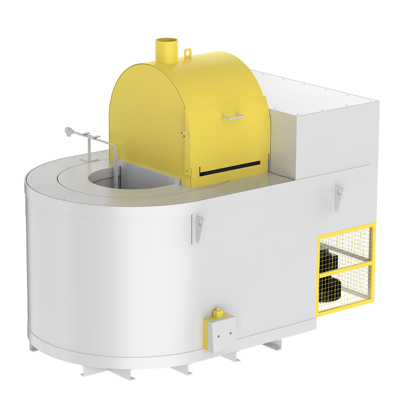
Detail the necessary square footage for safe operator movement. Workers need ample space during charging, skimming, and tapping procedures. Calculate operational swing clearances for heavy furnace lids and covers. They must never obstruct overhead cranes or adjacent walkways. Specify spatial allowances for heavy equipment access. Forklifts and overhead cranes require wide aisles for periodic refractory replacement and crucible changes.
Allocate a minimum of four feet of clearance around the charging door for manual operations.
Ensure lid swing arcs clear all structural columns, pipe drops, and electrical conduits.
Designate a fire-resistant laydown area for hot crucibles during replacement procedures.
Provide unobstructed access paths for refractory tear-out equipment and jackhammers.
Account for the length of dross skimming tools, which often exceed eight feet and require wide rear clearance.
Maintenance teams cannot work efficiently in cramped spaces. Burner tuning requires direct access to the gas train and combustion blower. Dross removal demands long-handled tools that need room to maneuver. Designing for maintenance access directly increases your equipment uptime.
Evaluate the placement of main gas headers and high-pressure regulators. Pressure reducing stations and individual furnace gas trains need secure mounting locations. Outline structural requirements for protecting gas lines. You must shield piping from thermal radiation and physical impact. Strategic routing prevents catastrophic damage from accidental molten metal spills. Route main gas headers high above the production floor. Drop lines should descend directly to the furnace gas train. Install rigid physical barriers around ground-level gas components. Forklift impacts cause severe damage to unprotected regulators. Shield all gas valves from radiant heat using reflective barriers. Ensure emergency shut-off valves remain easily accessible from multiple angles. Double block and bleed valve assemblies require specific horizontal pipe runs to function correctly.
Assess the structural capacity of the facility roof. You must support the weight of exhaust hoods, flues, and baghouses. Calculate the required makeup air volume accurately. Proper airflow ensures complete burner combustion. It maintains safe ambient air quality for operators working nearby. Fugitive emissions escape during charging and tapping operations. Canopy hoods capture these emissions effectively when sized correctly. You must balance exhaust volumes with incoming makeup air. Negative building pressure causes draft issues and poor burner performance. Install makeup air louvers strategically to avoid chilling the operators. Heavy baghouses often require independent structural steel supports. Do not overload existing roof trusses with new emission control equipment. A 10% positive pressure in the foundry prevents downdrafts through the exhaust stacks.
Balance the need for short metal transfer distances against radiant heat loads. Close proximity places thermal stress on die casting operators. It threatens sensitive CNC and PLC controls on the machinery. Evaluate the implementation of secondary furnace walls and physical heat shields. Targeted HVAC solutions in tight layouts provide additional operator protection. Radiant heat degrades electronic components rapidly. You must shield machine control panels from direct line-of-sight to the furnace. Install reflective aluminum barriers between the melting zone and the casting cell. Provide spot cooling for operators stationed near the holding crucible. Short transfer distances save energy but require aggressive heat management.
Compare the fixed footprint of automated transfer mechanisms. Monorail or robotic transfer systems require dedicated, permanent floor space. Manual or forklift-driven transfer ladles demand wider aisle requirements. Automated systems reduce labor but limit future layout flexibility. Monorails transport molten metal safely above operator heads. They require robust ceiling structures and precise alignment. Robotic ladles need safety fencing and interlocked access gates. These fixed systems dictate the exact placement of your furnaces. Forklift transfer allows you to reconfigure the shop floor later. Forklifts require wide turning radii and constant floor maintenance. Choose the system that matches your long-term production stability.
Develop phased installation timelines to integrate new furnace layouts. You must avoid halting existing die casting lines during upgrades. Plan for temporary holding solutions during the transition period. Proper scheduling minimizes disruptions to overall foundry output. Install new main gas headers during weekend shutdowns. Prepare the foundation and exhaust supports before the furnace arrives. Rent temporary electric holding furnaces to keep casting cells running. Execute the final tie-ins and commissioning during a planned holiday break. Staggering the installation prevents catastrophic production losses.
Ensure layout designs pass audits for North American standards. Familiarize yourself with FM Global, CFA, and NFPA 86 requirements. Mitigate risks by incorporating accessible emergency shut-off valves. Build spill containment pits or dry hearths directly into the floor plan. Safety codes dictate exact clearances for gas trains and electrical panels. You cannot compromise on these dimensions. Spill containment pits capture molten metal during a crucible failure. Size these pits to hold the entire capacity of the furnace. Install dry sand bases in the pits to prevent moisture explosions. Document all safety clearances on your final layout drawings.
Account for the ventilation requirements of the initial refractory dry-out phase. Curing generates significant moisture and fumes. Allocate sufficient time for these protocols before full production integration. Rushing the curing process destroys new refractory linings prematurely. Follow the manufacturer's exact curing schedule. This process often takes several days of continuous low-fire operation. Ensure exhaust systems run at full capacity during this phase. Monitor the external shell temperatures closely. Hot spots indicate refractory gaps or curing failures. Do not introduce solid metal until the curing cycle finishes completely. A typical ramp rate of 50°F per hour up to 1500°F requires dedicated operator supervision.
Initiate a comprehensive spatial and thermal audit of your current facility footprint to identify immediate bottlenecks.
Engage structural and combustion engineers to validate gas routing and exhaust capabilities before purchasing equipment.
Map out forklift and crane traffic lanes using floor tape to simulate safe molten metal transfer routes.
Finalize equipment procurement only after confirming NFPA and local safety compliance with your insurance underwriter.
A: Minimize the distance to prevent temperature drops. We recommend keeping molten metal transfer times under 60 seconds. You must maintain safe radiant heat clearances. Ensure enough space exists for secondary protective walls to shield operators and machine controls from thermal degradation.
A: Calculate sizing based on your hourly casting weight and scrap return ratios. Factor in the refractory thickness requirements for your specific alloy. You must account for the physical constraints of the charging and tapping zones within your floor plan to ensure safe operator access.
A: These furnaces require dedicated combustion air intakes and flue gas exhausts. Ambient canopy hoods are necessary to manage fugitive emissions and excess heat. Proper ventilation ensures safe breathing air, optimal burner performance, and prevents negative building pressure issues.
A: Central bulk melting is generally more gas-efficient per pound of metal processed. It requires secondary energy for holding furnaces at the casting cell. Decentralized melting uses more gas overall but eliminates the need for complex transfer logistics and dedicated transport vehicles.
A: NFPA and FM standards dictate clear zones around high-pressure gas regulators, gas trains, and electrical panels. You must account for lid swing arcs and emergency egress routes. This typically requires a minimum of 3 to 5 feet of unobstructed space around all critical components.
A: Yes, retrofitting is possible. You must evaluate your existing gas pressure delivery systems first. Check the roof structural integrity for new exhaust systems. Verify that floor load capacities can support heavier refractory-lined units without requiring extensive foundation reinforcement.
