
EMAIL:
lh@longhuamachine.com
TELL/whatsapp:
+8619305527239  English English
Views: 0 Author: Site Editor Publish Time: 2026-08-21 Origin: Site


Inconsistent die temperatures directly correlate with elevated scrap rates, dimensional instability, and premature tool failure in die casting operations. Selecting a die casting temperature control unit based on guesswork or outdated heuristics results in two expensive outcomes. Undersized units fail to extract heat during rapid cycles, causing soldering and porosity. Oversized units inflate capital expenditure and energy consumption without yielding process improvements. To achieve stable thermal equilibrium, engineers must evaluate capacity through a precise calculation of heating requirements, cooling loads, pump dynamics, and heat transfer mediums. Relying solely on machine tonnage is no longer sufficient for modern, high-speed manufacturing environments. You must calculate shot weight, alloy crystallization temperature, cycle time, and external cooling factors to specify the correct Temperature Control Unit.
Capacity is multifaceted: True TCU capacity is not just heater kilowatt (kW) rating; it requires balancing heating power, cooling capacity, and pump flow rate against the specific thermal load of the die.
Tonnage provides a baseline, but thermodynamics dictate final specs: While machine tonnage (e.g., 18 kW for 100-200 tons) offers a starting heuristic, accurate sizing requires calculating shot weight, alloy crystallization temperature, cycle time, and external cooling factors like die spray.
Pump performance dictates heat transfer: A high-capacity heater or heat exchanger is useless if the pump cannot overcome the pressure drops of complex, restrictive mold cooling temperature control channels.
Medium selection restricts operating limits: Oil-based units operate safely up to 320°C for high-temperature alloys, while pressurized water units offer superior heat transfer coefficients but are limited by pressure-temperature curves.
Maintaining die surface temperatures within a narrow, specified tolerance requires dynamic thermal regulation. A properly sized unit absorbs massive thermal shocks and dissipates heat rapidly. You must cool the die from peak fill temperatures of approximately 1000°F down to ejection temperatures below 500°F within seconds. Achieving this requires a system capable of switching seamlessly between intense heating and aggressive cooling phases depending on the exact moment in the casting cycle.
Before molten metal touches the die surface, the tool must reach an optimal operating temperature. Injecting molten aluminum or magnesium into a cold H13 tool steel die causes severe thermal shock. This sudden expansion leads to premature heat checking, surface cracking, and catastrophic tool failure. Cold dies also cause the molten alloy to solidify prematurely, resulting in cold shuts, misruns, and poor surface finishes. The heating phase relies on the unit's kilowatt capacity to circulate hot fluid through the die blocks. This gradually raises the steel mass to a uniform temperature, typically between 350°F and 500°F, before the first shot is fired. If the heater is undersized, the machine sits idle for hours waiting for the tool to reach a safe operating temperature, destroying overall equipment effectiveness.
Once production begins, the primary function shifts from heating to cooling. The system extracts latent heat from the injected alloy to solidify the casting rapidly and uniformly. Molten metal is poured at temperatures 50° to 70° higher than its crystallization temperature to ensure complete mold filling. As the metal changes state from liquid to solid, it releases an enormous amount of thermal energy. The temperature control system removes this exact amount of energy during every single cycle to prevent the die from overheating. If the cooling capacity is insufficient, the die temperature climbs with each successive shot until the process fails.
When a unit cannot extract heat fast enough, localized hot spots develop. These hot spots cause the casting to shrink unevenly during solidification, leading to severe shrinkage porosity and dimensional distortion. Excessive die temperatures cause the molten aluminum to solder to the tool steel, requiring machine downtime for manual polishing and die repair. Oversized capacity leads to operational inefficiencies. Massive pumps and oversized heaters consume unnecessary electricity, take up valuable floor space, and force the facility to manage larger volumes of heat transfer fluids without delivering any tangible improvement to part quality.
Determining the correct size for a thermal management system requires engaging with the actual thermodynamics of the casting process. Historical data provides a starting point, but modern die casting demands rigorous mathematical validation of the thermal load.
Industry-standard starting points for single-zone heating capacity are often based on the clamping force of the die casting machine. Typical baseline recommendations include:
100 to 200 tons requires approximately 18 kW of heating capacity.
300 to 400 tons requires approximately 24 kW of heating capacity.
500 to 600+ tons requires 24 kW to 36 kW, often necessitating a transition to multi-zone systems.
800 to 1200 tons requires multiple 36 kW units to manage the massive steel blocks.
Machine tonnage only dictates the maximum physical size of the die and the clamping force available to resist injection pressure. It ignores critical thermodynamic variables such as shot weight, cycle time, die complexity, and environmental variables. A 400-ton machine running a heavy, thick-walled part at a slow cycle time has a drastically different thermal profile than the same machine running a thin-walled, lightweight part at a rapid cycle time.
Engineers calculate the total heat energy introduced into the system and the rate at which it must be removed. This requires evaluating several interconnected variables through specific thermodynamic formulas.
The foundation of the thermal load calculation is the mass of the alloy injected per cycle. You calculate the total heat energy introduced based on the shot weight, which includes the biscuit, runners, and overflows. You must factor in the specific heat capacity and the latent heat of fusion of the chosen alloy. Aluminum has a high latent heat of fusion, meaning it releases a massive amount of energy as it solidifies. This requires significantly more cooling capacity than an equivalent weight of zinc.
To calculate the exact thermal load, follow these engineering steps:
Determine the total shot weight in pounds or kilograms.
Identify the pouring temperature and the target ejection temperature to find the required temperature drop (Delta T).
Multiply the shot weight by the alloy's specific heat capacity and the Delta T to find the sensible heat.
Multiply the shot weight by the alloy's latent heat of fusion.
Add the sensible heat and latent heat together to determine the total BTU or Joules introduced per shot.
Time is the denominator in the power equation. Faster cycle times drastically increase the required cooling capacity of the equipment. If a die introduces 3,000 BTUs of heat per shot, and the cycle time is 60 seconds, the system must remove 3,000 BTUs per minute. If the cycle time is reduced to 30 seconds to increase production throughput, the system must now remove 6,000 BTUs per minute. Cutting the cycle time in half doubles the required cooling capacity. Failure to account for aggressive cycle times results in a system that quickly overheats during continuous production.
External cooling factors play a massive role in the overall thermal balance. You must factor in the external cooling contribution of die lubricants. The die surface cools rapidly during the die spray cycle as the water-based lubricant flashes into steam. A significant portion of the heat is removed externally. The internal cooling capacity must be sized for the net thermal load. If you calculate the internal cooling requirements based on the total heat introduced by the metal without subtracting the heat removed by the die spray, you will drastically oversize the internal cooling heat exchangers.
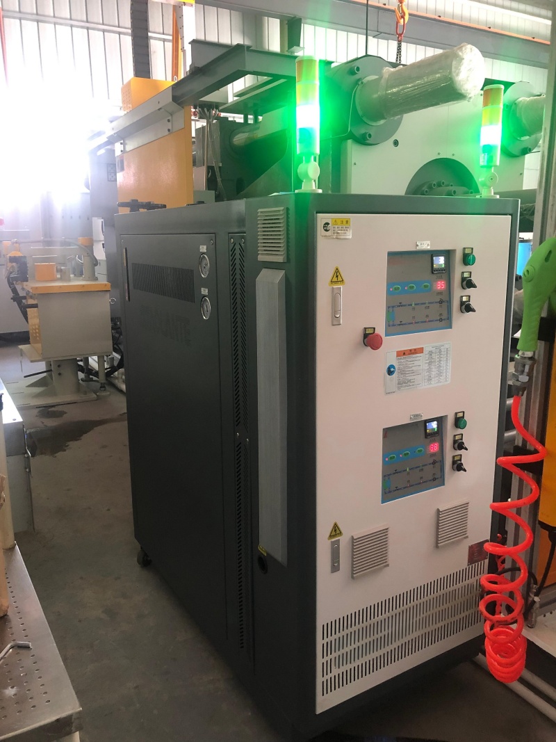
A common engineering oversight is focusing entirely on heating kilowatts and cooling heat exchanger sizes while neglecting the fluid delivery system. A high-capacity heater or massive cooling valve is useless if the thermal fluid cannot be physically transported to the die surface where the heat exchange occurs. Pump performance is the absolute bottleneck of thermal management.
Efficient heat transfer inside a die casting mold relies on fluid dynamics. Turbulent flow is mandatory for efficient mold cooling temperature control. When fluid flows in a laminar state, a boundary layer of stagnant fluid forms against the channel wall. This boundary layer acts as an insulator and destroys heat transfer efficiency. To break this boundary layer, the fluid must achieve a turbulent state, mathematically defined by a Reynolds number greater than 4000. Achieving this requires a specific minimum flow rate through the specific diameter of the cooling channels.
Pump flow rate determines the temperature delta (ΔT) between the inlet and outlet of the die. If the flow rate is insufficient, the fluid absorbs heat too slowly and remains in the die too long. This results in a high ΔT, meaning the fluid entering the die is much colder than the fluid exiting the die. A high ΔT creates uneven die temperatures, leading to warped parts and inconsistent dimensions. A properly sized pump ensures high flow velocity, minimizing the ΔT and maintaining a uniform temperature profile across the entire tool surface.
Theoretical flow rates are derailed by the physical realities of die design. Modern tooling utilizes conformal cooling, bubblers, baffles, and complex internal geometries to reach isolated hot spots near core pins and thick wall sections. These intricate pathways create massive flow resistance and significant pressure drops. A pump rated for 50 GPM at open discharge might drop to 5 GPM when forced through a series of 1/4-inch bubbler tubes.
Engineers evaluate pump curves rigorously. You match the pump's maximum pressure and flow characteristics to the specific resistance of the die's tempering channels. High-pressure centrifugal pumps or positive displacement pumps are required to overcome the severe restrictions found in complex die casting molds. Specifying a pump based solely on its maximum flow rate without analyzing its performance at high head pressure results in stagnant fluid and localized die overheating.
The choice of heat transfer fluid dictates the physical construction of the equipment, the maximum operating temperatures, and the overall efficiency of the thermal exchange. Thermal oil and pressurized water possess distinct thermodynamic properties that make them suitable for different casting applications.
Thermal Fluid Specifications
Category | Max Operating Temp | Heat Transfer Efficiency | Common Applications | Maintenance Risks |
|---|---|---|---|---|
Synthetic Oil | Up to 320°C (608°F) | Moderate (Lower specific heat) | Aluminum, Magnesium, Thin-wall parts | Thermal cracking, fluid degradation, leaks |
Pressurized Water | 160°C - 200°C (320°F - 392°F) | Excellent (High thermal conductivity) | Zinc, Aggressive Aluminum cooling | Scaling, corrosion, high-pressure safety |
Unpressurized Water | Below 95°C (203°F) | Excellent | Zinc, Plastics, Low-temp processes | Biological growth, minor scaling |
Thermal oil systems are the traditional standard for high-temperature die casting. These systems handle synthetic or mineral-based heat transfer fluids. They reach operating temperatures up to 320°C (608°F) without boiling or requiring high-pressure containment vessels. This makes them inherently safer from a pressure-explosion standpoint compared to high-temperature water systems.
Oil units are utilized for high-temperature aluminum and magnesium die casting where elevated die temperatures facilitate metal flow in thin-walled components. Keeping the die exceptionally hot prevents the metal from freezing before it completely fills intricate cavity details. Oil has a lower specific heat and lower thermal conductivity compared to water. It absorbs and transfers heat less efficiently. To achieve the same cooling effect as water, an oil system requires significantly larger pumps to move a higher volume of fluid. Thermal oil is subject to degradation. Exposure to high heat and oxygen causes the oil to break down, forming sludge and carbon deposits that coat the inside of heaters and die channels, insulating the system and destroying efficiency.
Water is thermodynamically superior to oil in almost every measurable metric for heat transfer. It has a higher specific heat, higher density, and better thermal conductivity. Standard unpressurized units operate below 95°C, but specialized pressurized water units achieve operating temperatures up to 160°C - 200°C. Reaching these temperatures requires maintaining the system under high pressure to prevent the water from boiling into steam.
These systems are used in zinc die casting or specific aluminum applications requiring aggressive cooling to achieve rapid cycle times. The superior heat transfer coefficient of water allows for faster cooling, enabling shorter solidification times and higher production rates. High-temperature water systems carry a risk of scaling and corrosion. Minerals in untreated facility water precipitate out at high temperatures, clogging narrow cooling channels and destroying pump seals. Operating pressurized water systems requires rigorous water quality management, often necessitating dedicated reverse osmosis systems and chemical dosing to maintain neutral pH and low conductivity.
Die casting molds rarely have uniform thermal profiles. The area near the injection sprue absorbs massive amounts of heat, while the outer edges of the cavity run cold. Deciding how many independent temperature zones are required is a critical step in specifying the equipment.
A single-zone system provides one supply temperature and one return line for the entire die. This approach offers lower upfront cost and simpler maintenance. Single-zone setups are suitable for simple dies with uniform wall thickness, smaller parts, and lower tonnage machines where the thermal load is relatively balanced. Forcing the entire die to operate at a single fluid temperature requires compromising between the hot and cold areas of the tool.
Multi-zone configurations contain two or more independent heating, cooling, and pumping circuits within a single chassis. Engineers set independent temperature controls for the fixed half of the die, the moving half, or specific, highly stressed core pins. The fixed half, which absorbs more heat from the shot sleeve, is run at a colder fluid temperature. The moving half is run hotter to balance the overall thermal expansion of the tool.
Granular control directly leads to the reduction of localized soldering in high-velocity gate areas. By applying aggressive cooling specifically to the sprue and runners while maintaining elevated temperatures in thin-walled cavity sections, engineers optimize cycle times in complex geometries. Multi-zone systems eliminate the need to slow down the entire machine just to wait for one massive core pin to cool. This maximizes overall production efficiency and extends tool life by minimizing internal thermal gradients.
Deploying advanced thermal management equipment introduces operational variables into the facility. Anticipating maintenance requirements and integration challenges ensures long-term reliability.
The primary risk to any thermal control system is the degradation of the heat transfer medium. Thermal cracking of heat transfer oil creates carbon buildup that destroys heat transfer efficiency and damages mechanical pump seals. In water systems, scaling acts as an insulator, and corrosion eats away at internal components.
Facilities must specify units with continuous fluid filtration systems to capture suspended solids and sludge. Implementing automatic cooling down sequences before shutdown is mandatory. Turning off a pump while the heaters are still glowing hot instantly scorches the stagnant oil. Utilizing magnetic drive pumps eliminates the risk of mechanical seal leaks, which are a primary source of downtime and safety hazards in high-temperature oil applications.
Operating the equipment in a silo leads to process drift and thermal instability. If the unit operates independently of the die casting machine, operators cannot correlate thermal data with injection parameters, making root cause analysis of casting defects impossible.
Evaluate units equipped with modern communication protocols such as OPC UA, Euromap, or Profibus. These protocols allow for direct integration with the die casting machine's PLC, enabling centralized control and data logging. Ensure the unit utilizes advanced PID control algorithms and Solid State Relays to maintain die temperatures within strict limits. Modern systems provide real-time monitoring of flow rates, supply/return temperatures, and system pressure, triggering automatic alarms if flow drops below the critical threshold required for turbulent heat transfer.
Audit your current die temperatures and cycle times across all active production cells to establish a baseline thermal profile.
Calculate the theoretical net thermal load of your most demanding tool using specific heat formulas and actual shot weights.
Consult with equipment manufacturers to run flow and thermal simulations on your conformal cooling channel designs.
Specify magnetic drive pumps and continuous fluid filtration systems on all new equipment to eliminate mechanical seal failures.
A: A 400-ton machine typically utilizes a 24 kW single-zone system as a baseline. A 600-ton machine generally requires 24 kW to 36 kW, often split into a multi-zone configuration to handle the larger die mass. Actual requirements depend heavily on shot weight and cycle time.
A: A standard chiller only provides cooling, typically delivering fluid at temperatures below ambient. A temperature control unit features integrated high-capacity heaters, specialized pumps, and cooling valves. It actively heats the die before production and precisely regulates high operating temperatures up to 320°C.
A: Oil is the traditional choice for aluminum due to its ability to safely reach 320°C without high pressure, preventing premature metal freezing. Pressurized water up to 200°C is increasingly used for its superior heat transfer efficiency, allowing for faster cycle times if water quality is managed.
A: Heating capacity generates energy, but the pump transfers it. Without sufficient flow rate, fluid cannot achieve the turbulent state required to efficiently strip heat from the die walls. Low flow results in stagnant fluid, high temperature differentials, and localized hot spots.
A: The ideal temperature difference between the fluid entering and exiting the die should be kept between 2°C and 5°C. A low temperature delta indicates high flow velocity and efficient heat transfer, ensuring uniform temperature distribution across the entire die surface.
A: Multiply the total shot weight by the alloy's specific heat capacity and the temperature difference between the pouring temperature and ejection temperature. Add the latent heat of fusion. Divide this total heat energy by the cycle time to determine the required heat removal rate.
