
EMAIL:
lh@longhuamachine.com
TELL/whatsapp:
+8619305527239  English English
Views: 0 Author: Site Editor Publish Time: 2026-08-03 Origin: Site


Inadequate flow rates in mold thermal management create hidden production costs that quietly erode manufacturing efficiency. When fluid velocity drops below critical thresholds, cycle times extend, thermal inconsistencies multiply, and scrap rates spike due to part warpage, poor surface finish, or compromised plastic melt flow. Many operations mistakenly size a Mold Temperature Controller based solely on its heating or cooling kilowatt capacity, completely ignoring pump performance and actual volumetric flow requirements. Without sufficient flow to overcome the system's internal resistance, even the highest-capacity heater cannot effectively transfer thermal energy to or from the mold surface. Evaluating equipment requires a strict technical assessment of flow requirements, pump curves, and system architecture. The actual flow delivered to the cooling channels is dictated by mold geometry, material specifications, and real-world pressure drops. By calculating precise flow requirements, engineering teams can select the exact equipment architecture needed to maintain process stability.
Flow Dictates Heat Transfer: Achieving turbulent flow (Reynolds number > 4,000) is non-negotiable for optimal heat transfer; flow rate is the primary driver of this state.
Nameplate vs. Actual Flow: A controller’s maximum rated flow rate is measured at zero pressure. Actual operational flow is dictated by the system's pressure drop and the specific pump performance curve.
Melt Flow Dependency: The temperature of the mold has a powerful, direct impact on the flow of the melted plastic during the filling phase; precise TCU flow rates ensure the mold temperature remains stable enough to prevent premature freezing or short shots.
Application Specificity: Small injection molds typically require 30 to 60 L/min, while large automotive or die casting applications easily exceed 80 to 200 L/min.
Intelligent Monitoring is Critical: Modern operations require intelligent mold temperature control to dynamically monitor flow rates, detect channel blockages, and maintain process repeatability.
Heat transfer efficiency in any molding process relies heavily on fluid velocity. When a heat transfer fluid moves slowly through a cooling channel, it flows in parallel layers. We call this state laminar flow. Laminar flow creates a stagnant boundary layer of fluid against the channel wall. This boundary layer acts as a thermal insulator, severely restricting the transfer of heat between the mold steel and the fluid. You can have the coldest water in the plant, but if it moves too slowly, the mold stays hot.
To break this insulating layer, the fluid must move fast enough to create turbulence. Turbulent flow aggressively mixes the fluid, constantly replacing the fluid at the channel wall with fluid from the center of the channel. This continuous mixing acts as a thermal conductor, maximizing the heat transfer coefficient. The volumetric flow rate directly determines whether the fluid achieves this necessary velocity. If you walk up to a press and feel the return line, a low flow rate will often result in a massive temperature difference between the supply and return, indicating poor heat extraction.
The transition from laminar to turbulent flow is calculated using the Reynolds number (Re). This is a dimensionless metric that factors in fluid velocity, channel diameter, and the kinematic viscosity of the fluid. In mold cooling applications, a Reynolds number below 2,100 indicates laminar flow. A value above 4,000 guarantees fully turbulent flow. Because channel diameter is fixed by the mold design and fluid viscosity is dictated by the operating temperature, fluid velocity remains the only variable you can control.
Increasing the flow rate in Liters Per Minute (L/min) or Gallons Per Minute (GPM) directly increases fluid velocity. This drives the Reynolds number past the 4,000 threshold required for efficient thermal management. For example, pushing water through a standard 7/16-inch cooling line requires roughly 1.2 to 1.5 GPM per line just to hit that turbulent threshold. If your pump cannot deliver that volume across all lines simultaneously, you lose thermal control.
Flow rate stability directly correlates to uniform mold surface temperatures. During the injection phase, the temperature of the mold steel dictates how the melted plastic behaves as it fills the cavity. If inadequate flow causes hot and cold spots across the mold surface, the plastic melt will flow unevenly. Cold spots cause the material to freeze prematurely. This leads to high injection pressure demands, weld lines, and short shots.
Uniform temperatures maintained by turbulent flow ensure consistent melt flow. This minimizes differential shrinkage and residual stress in the final part. Maximizing heat extraction through high flow rates significantly reduces the cooling phase duration. Since cooling often represents 60% to 80% of the total cycle time, optimizing flow rate is the fastest way to increase machine output and improve part dimensional stability.
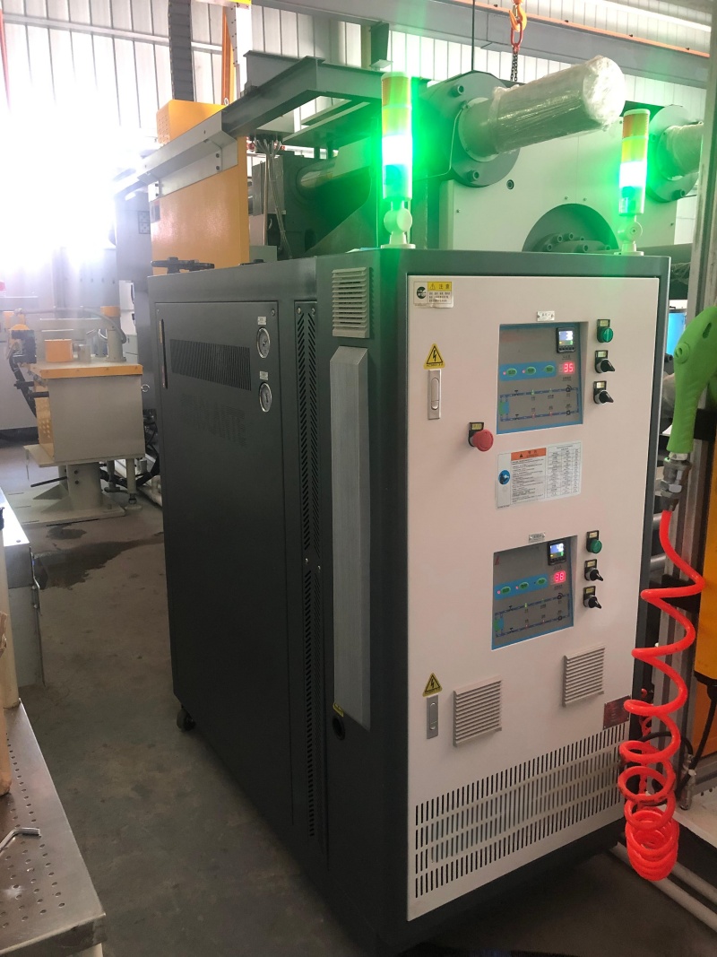
The physical design of the mold's internal channels dictates the volume of fluid required to maintain turbulent velocity. A larger diameter channel requires a significantly higher volumetric flow rate to achieve the same fluid velocity as a smaller channel. Internal surface roughness and the total length of the circuit also impact the resistance the fluid encounters. Baffles and bubblers, commonly used to cool deep cores, introduce massive flow restrictions that require higher pump pressure to overcome.
Channel routing strategies drastically alter flow demands. Series cooling circuits route fluid through a single, continuous path. This setup requires lower total flow from the pump but generates massive pressure drops. You need a high-pressure pump to push the fluid through a series circuit. Parallel cooling circuits split the fluid across multiple channels simultaneously. This drastically reduces the pressure drop but requires a massive total flow rate to ensure every individual branch maintains enough velocity to achieve turbulent flow.
The thermal load introduced into the mold depends entirely on the material being processed. Different polymers and metal alloys possess different specific heat capacities. They retain and release different amounts of thermal energy. Processing polycarbonate or high-temperature engineering resins introduces a higher thermal load than standard polypropylene. This requires a faster rate of heat removal.
This thermal load dictates the acceptable temperature difference (Delta T) between the fluid entering the mold and the fluid exiting it. A lower Delta T indicates a more uniform mold temperature. Precision parts demand a tight Delta T of 1°C to 2°C across the mold. Achieving this requires a substantially higher flow rate. If the flow rate is too low, the fluid absorbs too much heat as it travels, resulting in a high Delta T and uneven mold temperatures from the inlet to the outlet.
Pressure drop, or head loss, represents the resistance the fluid faces as it travels from the pump, through the system, and back. Every component in the loop contributes to this resistance. Internal mold channels, manifolds, quick-disconnect fittings, and restrictive hoses all destroy fluid pressure.
There is a strict inverse relationship between system pressure and flow rate. As resistance increases, the actual flow delivered by the pump decreases. Evaluating a mold temperature controller requires analyzing the manufacturer's pump performance curve. This curve plots flow rate against head pressure. A pump rated for 100 L/min at zero pressure might only deliver 20 L/min when connected to a restrictive mold circuit. Selecting equipment based on maximum theoretical flow rather than the flow available at the actual operating pressure guarantees failure on the production floor.
Determining the exact flow requirement begins with calculating the total heat load introduced by the injected material per hour. You must establish the baseline thermal requirement before looking at pump specs. Once you know the heat load, you can determine the required fluid velocity to remove that heat while maintaining a tight Delta T.
Follow these specific steps to calculate your required flow rate:
Calculate the total heat load (kW or BTU/hr) based on the material's specific heat, shot weight, and shots per hour.
Determine the target temperature rise (Delta T) allowed across the mold. Tighter tolerances require smaller Delta T values.
Calculate the required fluid velocity to achieve a Reynolds number over 4,000 based on your specific cooling channel diameters.
Convert that required fluid velocity into a volumetric flow rate (L/min or GPM) for a single channel.
Sum the flow requirements for all parallel circuits combined to find the absolute total flow the controller must provide.
Cross-reference this total flow requirement with the pump performance curve at your estimated system pressure drop.
Failing to aggregate these individual requirements results in thermally starved channels. If a mold features eight parallel channels, each requiring 10 L/min to achieve turbulence, the controller must deliver a minimum of 80 L/min at the specific pressure drop of that manifold system.
Equipment sizing varies wildly depending on the scale and complexity of the tooling. Small to medium injection molds generally require flow rates between 30 to 60 L/min. These molds are typically used for consumer electronics or precision medical components. In these applications, precision and rapid response times take priority over sheer fluid volume. The total thermal mass of the mold is relatively low, but the channels are often small and restrictive.
Large-scale automotive components, heavy industrial parts, and high-cavitation packaging molds present massive thermal loads. These applications frequently utilize extensive parallel manifold systems to cool large surface areas evenly. Flow requirements for these large tools easily exceed 80 to 200 L/min. Servicing these molds requires high-capacity centrifugal pumps capable of sustaining massive volumetric output without losing pressure across complex cooling networks.
Standard injection molding processes typically utilize water-based or pressurized water units operating at temperatures up to 180°C. Water is an exceptionally efficient heat transfer fluid. It has a high specific heat capacity and low kinematic viscosity. Because water flows easily and absorbs heat rapidly, standard centrifugal pumps are highly effective for most standard molds.
The primary engineering challenge in modern injection molding is balancing pump horsepower with flow rate to navigate complex conformal cooling channels. Additive-manufactured mold inserts often feature highly restrictive micro-channels. These channels require pumps with steep performance curves. Regenerative turbine pumps or high-pressure centrifugal pumps are necessary to maintain high pressure and push adequate flow through these tiny diameters.
Die casting environments present a significantly harsher thermal reality. Processing molten aluminum or magnesium requires mold temperatures that far exceed the capabilities of water. This necessitates the use of high-temperature thermal oil operating up to 350°C. When specifying a die casting mold temperature controller, engineers must account for the distinct physical properties of thermal oil.
Thermal oil possesses a much lower specific heat capacity than water. It absorbs less heat per unit of volume. Oil also has a significantly higher viscosity, making it harder to pump and more resistant to turbulent flow. To achieve the same heat transfer coefficient as a water system, an oil-based system requires drastically higher flow rates. You need specialized, high-pressure positive displacement pumps or heavy-duty magnetic drive centrifugal pumps. These pumps are designed specifically to move viscous fluids at extreme temperatures without cavitating or suffering mechanical seal failures.
Relying on theoretical pump curves and manual pressure gauges is no longer sufficient for high-yield manufacturing. Modern operations deploy intelligent mold temperature control systems equipped with ultrasonic or vortex flow meters. These sensors provide real-time, highly accurate volumetric flow data directly to the machine's PLC. This eliminates the guesswork associated with pressure-based flow estimation.
Coupling this real-time data with Variable Frequency Drives (VFDs) creates a dynamic, closed-loop thermal management system. A VFD-driven pump automatically adjusts its motor speed to maintain a precise, user-defined flow rate. If minor pressure fluctuations occur due to fluid viscosity changes during startup, the VFD instantly compensates. This guarantees process stability by ensuring continuous turbulent flow. It also drastically reduces energy consumption by only running the pump as hard as physically necessary.
Intelligent controllers transform thermal management from a reactive process to a proactive one. Over hundreds of production hours, cooling channels inevitably suffer from scale buildup, rust, or debris accumulation. This degradation slowly reduces the internal diameter of the channels. It exponentially increases pressure drop and silently chokes off the flow rate.
Advanced systems continuously monitor the baseline flow rate against the pump's energy draw. If the system detects a gradual drop in flow despite constant pump effort, it identifies the restriction. The controller triggers predictive maintenance alarms long before the thermal degradation impacts part quality or disrupts plastic melt flow. This capability prevents unexpected downtime and protects expensive tooling from thermal shock and fatigue.
The most frequent procurement error is trusting the nameplate maximums printed on a specification sheet. A system may appear perfectly capable of holding tight temperatures at low flow on paper. However, it will fail catastrophically in the real mold if it cannot overcome the actual physical pressure drop of the circuit. Theoretical calculations assume ideal conditions. Real-world molds feature sharp turns, rough surfaces, and complex manifolds that destroy fluid velocity. You must evaluate equipment based on its performance at the expected operating pressure, not its zero-resistance maximum.
Facility managers often attempt to solve heating issues by purchasing units with massive kilowatt heating capacities while settling for standard, low-horsepower pumps. This creates a scenario where the controller rapidly reaches its setpoint internally, but the mold remains thermally starved. The heater has the energy, but the undersized pump lacks the physical force to transport that energy into the mold steel. The controller cycles on and off perfectly while the actual mold surface temperature fluctuates wildly. This leads to immediate part defects and dimensional instability.
Even the most powerful pump cannot overcome poor external plumbing. Undersized hoses, excessive 90-degree elbows, and restrictive quick-connect fittings create artificial pressure drops. These restrictions cripple the actual flow rate delivered to the tool. A standard 1/2-inch quick disconnect might have an internal orifice of only 1/4-inch. Pushing fluid through this bottleneck destroys pressure and velocity before the fluid even enters the mold. Auditing external plumbing is just as critical as sizing the pump.
Common Flow Restriction Factors in Mold Cooling Systems
Restriction Source | Impact on System Performance | Engineering Mitigation Strategy |
|---|---|---|
Quick-Disconnect Fittings | Internal orifices are often much smaller than the hose diameter, creating severe bottlenecks and pressure loss. | Specify full-flow or oversized quick-disconnects. Measure internal diameters, not just thread sizes. |
Series Cooling Layouts | Forces fluid through a long, continuous path, compounding pressure drop and causing high Delta T. | Redesign channels into parallel circuits using external manifolds to reduce total head pressure. |
Scale and Rust Buildup | Reduces internal channel diameter over time, exponentially increasing resistance and destroying turbulent flow. | Implement routine descaling maintenance and utilize intelligent controllers with low-flow alarms. |
Undersized Supply Hoses | Creates immediate artificial head pressure before fluid reaches the mold, starving the entire system. | Match hose internal diameter to the main manifold inlet size. Keep hose lengths as short as possible. |
Audit your current mold pressure drops using inline analog or digital gauges on the supply and return manifolds.
Calculate the required Reynolds numbers for your most demanding tools to establish baseline fluid velocity requirements.
Request actual pump performance curves from equipment manufacturers and map your calculated pressure drop against them.
Replace standard restrictive quick-disconnect fittings with full-flow alternatives to instantly recover lost volumetric flow.
A: The minimum flow rate depends entirely on the cooling channel diameter and fluid viscosity. You must achieve a Reynolds number greater than 4,000. For a standard 10mm channel using water, this typically requires a fluid velocity of roughly 1.5 meters per second. You must calculate the specific volumetric flow rate for each individual channel based on these variables.
A: Pressure drop acts as resistance against the pump. As the resistance from channels, hoses, and fittings increases, the volume of fluid the pump can push decreases. A controller rated for 100 L/min at zero pressure will deliver significantly less flow when connected to a highly restrictive mold circuit.
A: Flow rate dictates mold surface temperature uniformity. If low flow causes cold spots on the mold, the injected plastic melt will freeze prematurely in those areas. This restricts the melt flow, requiring higher injection pressures and frequently causing defects like short shots and prominent weld lines.
A: Thermal oil has a lower specific heat capacity and higher viscosity than water. Because it absorbs less heat and is harder to pump, an oil-based system requires a significantly higher volumetric flow rate and a more robust, high-pressure pump to achieve the same heat transfer efficiency as a water system.
A: The most accurate method is utilizing inline ultrasonic or vortex flow meters installed on the return lines of the cooling circuits. These devices provide real-time volumetric data regardless of pressure fluctuations, offering precise insight into actual channel performance without introducing mechanical restrictions.
A: Series lines route fluid through one long path, requiring high pump pressure but lower total volume. Parallel lines split the fluid across multiple paths simultaneously, drastically reducing pressure drop but requiring a massive total flow rate from the pump to ensure every individual line maintains turbulent velocity.
