
EMAIL:
lh@longhuamachine.com
TELL/whatsapp:
+8619305527239  English English
Views: 0 Author: Site Editor Publish Time: 2026-08-28 Origin: Site


Thermal processing equipment often becomes the hidden bottleneck on the die casting floor. Mismatched furnace capacities either starve the die casting machine (DCM) or waste energy through excessive thermal idling. Incorrect furnace sizing introduces severe operational risks. Undersizing leads to rapid temperature drops, causing short pours and forcing costly machine downtime. Oversizing creates a different set of problems. It results in unnecessary energy consumption and bloated floor space utilization. Prolonged metal holding times also severely degrade alloy quality. Extended heat exposure drives hydrogen absorption and accelerates oxide formation on the melt surface. These metallurgical flaws ultimately compromise the tensile strength and hardness of your final cast parts. We present a systematic, data-driven framework for calculating exact thermal load requirements. You will learn how to evaluate equipment specifications accurately and integrate the right furnace into an automated die casting cell to balance high-speed production with strict metallurgical integrity.
Capacity is a Dual Metric: Proper sizing requires calculating both the continuous melt rate (lbs/hr) and the total holding capacity based on the DCM's maximum shot weight and cycle time.
Metal Quality is Time-Dependent: Oversized holding capacities increase the risk of alloy degradation; the furnace must balance continuous availability with optimal metal turnover rates to ensure required mechanical properties.
Automation Dictates Design: Modern high-volume cells require seamless integration between the furnace and automated metal handling systems (e.g., ceramic ladles, dosing pumps) to maintain consistent cycle times.
Standard vs. Custom Configurations: While standard BTU and capacity ranges suit many applications, complex cell architectures often necessitate custom furnace designs to meet specific spatial and thermal criteria.
Every successful die casting operation relies on precise thermal management. You must define baseline expectations for your thermal processing equipment before pouring a single ounce of metal. Precise temperature control prevents excessive metal loss and stops rapid dross formation on the bath surface. An uninterrupted metal supply keeps the DCM running at peak efficiency. Preserving specific metal properties remains your most critical objective on the floor. Tensile strength and hardness dictate the final part quality, and the furnace acts as the heart of this entire process. It dictates the rhythm and reliability of the casting cycle.
Facilities utilize different cell architectures based on production volume and alloy variations. Many plants deploy a standalone Crucible Melting and Holding Furnace at each work center. This setup provides maximum flexibility for frequent alloy changeovers. Other facilities rely on portable, point-of-use holding furnaces fed by a massive central reverberatory melter. Central melting works well for single-alloy, high-volume operations. However, moving molten metal across a plant floor via forklifts and transfer ladles introduces severe temperature loss. It also increases the risk of oxidation during transit. Standalone cell furnaces eliminate these transfer risks entirely by keeping the melting and holding phases within arm's reach of the shot sleeve.
Modern furnaces often perform dual functionality, which complicates their design. Melting raw ingot requires massive, aggressive energy input from the burners. Holding molten metal demands precise, gentle temperature stability to prevent overheating. Combining these two distinct functions in a single crucible unit requires careful capacity balancing. If an operator introduces too much cold ingot at once, the bath temperature plummets instantly. The heating elements must then work overtime to recover the lost heat. This recovery period delays production, causes short pours, and heavily stresses the refractory lining.
Furnace reliability directly impacts Overall Equipment Effectiveness (OEE) across the entire plant. Temperature stability correlates directly to scrap reduction. When metal temperatures fluctuate, shrinkage and porosity defects multiply rapidly in the die. Consistent thermal control boosts machine uptime significantly and drives the evolution of advanced metal handling systems.
Reduces scrap rates by maintaining metal temperature within a strict 10-degree operational window.
Eliminates waiting time for the DCM by ensuring a constant, reliable reservoir of liquid metal.
Prevents die thermal shock by delivering consistent metal temperatures directly to the shot sleeve.
Lowers maintenance downtime by utilizing properly sized heating elements that do not overwork during recovery phases.
You must calculate your hourly metal demand accurately using hard data from the shop floor. Start by determining the total shot weight. Do not just weigh the finished part. This figure must include the cast part, the biscuit, the runner system, and all overflows. Multiply this total shot weight by your maximum shots per hour. This formula provides your baseline continuous melt rate requirement. For example, a 12-pound total shot running at 50 shots per hour demands 600 pounds of metal hourly. You cannot size your furnace based on this raw number alone, as it leaves zero room for operational realities.
Translate this metal demand into a precise thermal load calculation. Proper BTU sizing ensures the burner or heating elements keep pace with the DCM during peak production. Always add a 15-20% capacity buffer to your final calculation. This buffer accounts for operational surges and provides necessary thermal recovery time after operators load cold ingots or heavy scrap. Without this buffer, the furnace will slowly lose ground during a long production shift. The metal temperature will eventually drop below the acceptable casting range, forcing you to halt the DCM until the furnace catches up.
Measure the exact weight of the entire shot using a calibrated floor scale.
Record the fastest possible cycle time the DCM can mechanically achieve.
Calculate the raw hourly metal consumption based on continuous operation.
Apply a 20% thermal buffer to determine the required continuous melt rate.
Verify the burner BTU output matches the energy required to melt this specific volume of aluminum.
Industry-standard ratios dictate safe, reliable furnace design. Holding capacity typically measures three to five times the hourly melt rate. This specific ratio ensures thermal stability across all shifts. When operators introduce cold ingots, the large volume of molten metal absorbs the thermal shock. The overall bath temperature barely fluctuates because the thermal mass is so large. Consider real-world heavy-duty setups for perspective. Pairing a 2,000 lbs/hr melt rate with an 8,000 lbs holding zone illustrates proper scaling. This massive thermal mass protects the casting process from sudden temperature dips.
Deviating from these established ratios introduces severe operational risks. If the holding capacity is too small relative to the melt rate, thermal shock occurs frequently. The temperature drops rapidly below the liquidus line. Sludge begins to form at the bottom of the crucible. Iron, manganese, and chromium precipitate out of the alloy and settle. This sludge ruins the crucible, destroys heating efficiency, and causes hard spots in your castings that will break machining tools downstream. You must respect the holding-to-melt ratio to maintain metallurgical harmony.
Evaluate your specific virgin ingot to in-house scrap ratio. Melting runners and biscuits impacts your required energy differently than melting pure, clean ingot. Different material densities alter the internal thermal dynamics of the bath. Dense, uniform ingots sink quickly and melt predictably. Porous scrap or thin runners melt faster but introduce significantly more oxide skins and trapped dirt into the bath. You must account for these variations when sizing the equipment and planning your fluxing routines.
Scrap returns also affect thermal recovery time. Large, thick biscuits absorb heat rapidly from the surrounding melt. If your process generates massive runners due to complex die designs, you need a larger holding capacity to buffer the temperature drop. Always calculate your capacity based on the worst-case scenario. Assume the highest possible scrap return rate when designing your thermal load requirements to ensure the furnace never bottlenecks the cell.
Furnace Capacity Calculation Variables
Variable | Definition | Impact on Sizing |
|---|---|---|
Total Shot Weight | Combined weight of part, runner, biscuit, and overflows. | Establishes the baseline volume of metal removed per cycle. |
Cycle Time | Total time to complete one full casting shot. | Determines the frequency of metal depletion from the bath. |
Scrap Ratio | Percentage of remelted runners versus virgin ingot. | Alters thermal recovery speed and potential oxide generation. |
Thermal Buffer | Additional 15-20% capacity added to baseline calculations. | Prevents temperature starvation during continuous heavy production. |
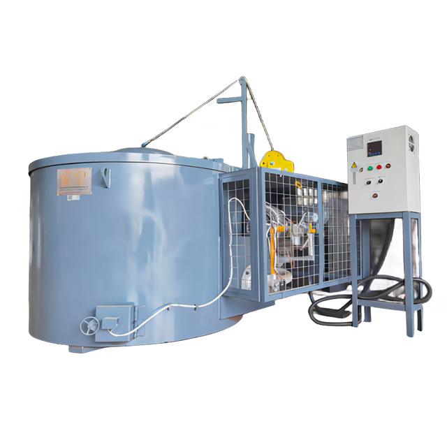
Melting aluminum presents highly specific metallurgical challenges on the floor. Common die casting alloys like 380, 390, or 413 require precise handling. Aluminum possesses a very high affinity for hydrogen gas. As the metal temperature rises above 1250°F, it absorbs hydrogen rapidly from the surrounding atmosphere, damp tools, or moisture on cold ingots. Aluminum also undergoes rapid oxidation when exposed to air, creating a tough skin of dross on the surface. These metallurgical contaminations directly degrade your final product. They lower tensile strength, reduce overall hardness, and increase internal porosity levels drastically, leading to pressure test failures.
Crucible design heavily influences heat transfer and metal purity. You must choose the right material for your specific application. Silicon carbide crucibles offer excellent thermal conductivity. They transfer heat rapidly from the burners into the aluminum bath, reducing energy waste. Clay graphite crucibles provide different benefits, often resisting certain aggressive chemical fluxes better than silicon carbide. An optimal aluminum crucible melting furnace minimizes contamination risks through uniform heating. It prevents localized hot spots on the crucible walls where excessive hydrogen absorption and corundum growth typically occur.
Monitor bath temperatures strictly with calibrated thermocouples to prevent hydrogen gas absorption.
Minimize surface agitation during ladling to slow down rapid oxidation rates.
Select silicon carbide crucibles for maximum thermal transfer efficiency in high-volume cells.
Use appropriate rotary degassing equipment to remove trapped hydrogen before pouring.
Scrape the crucible walls daily to prevent oxide buildup and destructive corundum growth.
Analyze crucible wear patterns carefully in high-capacity melting scenarios. Continuous thermal cycling stresses the refractory material constantly. Expanding during heat-up and contracting during cool-down eventually causes micro-cracks in the crucible structure. Corrosive fluxes used to clean the aluminum and remove oxides also attack the crucible walls chemically. You must select refractory materials based on alloy corrosiveness and your specific fluxing regimen. Operating temperatures also dictate your material choice. Pushing a furnace to higher temperatures to compensate for undersizing accelerates chemical wear exponentially.
Proper material selection extends maintenance cycles significantly. It prevents unexpected catastrophic failures, like a crucible blowout, during a production run. Establish a strict, documented inspection routine. Look for erosion at the metal line where flux attacks the wall. Check for sludge buildup at the bottom using a steel rod. Sludge acts as a thermal insulator, forcing the burners to work harder to push heat through the bottom of the crucible. This localized overheating destroys the crucible prematurely. Regular maintenance ensures the furnace delivers consistent thermal performance over its entire operational lifespan.
Evaluate off-the-shelf standard ranges first before looking at custom builds. Standard BTU outputs and crucible sizes suit many conventional die casting applications. Manufacturers design these units for typical shot weights and standard DCM cycle times. They offer proven reliability, faster installation times, and readily available replacement parts. If your process falls within normal parameters, a standard unit provides excellent performance. It simplifies spare parts procurement and makes routine maintenance training straightforward for your floor operators.
However, custom furnace designs become mandatory for complex, highly automated cells. Specialized alloy requirements often dictate unique thermal profiles or multi-chamber designs. You might need specialized degassing baffles or custom dip well geometries to accommodate specific robotic ladles. Restrictive footprint limitations also require tailored equipment dimensions. If your plant floor layout is tight, a standard furnace might impede forklift traffic or block robotic arm movement. In these scenarios, custom engineering ensures seamless physical and thermal integration with your existing infrastructure.
Standard vs. Custom Furnace Configurations
Configuration Type | Ideal Application Scenario | Primary Advantage |
|---|---|---|
Standard Off-the-Shelf | Conventional cells with standard shot weights and ample floor space. | Rapid deployment and easy access to standardized spare parts. |
Custom Geometry | Tight floor layouts requiring specific dip well locations for robotics. | Prevents interference with automated arms and forklift traffic. |
Custom Thermal Profile | Specialized alloys requiring strict degassing or multi-chamber holding. | Maintains exact metallurgical properties for high-spec aerospace or automotive parts. |
Examine physical integration requirements closely before installation. Dip well dimensions must accommodate robotic arms perfectly. The ladle needs sufficient clearance to enter the bath, scoop the metal, and exit without striking the refractory walls or the crucible edge. Smooth mechanical movements prevent unnecessary metal agitation, which creates dross. Maintaining a consistent metal level is absolutely non-negotiable for automation. If the metal level drops even an inch, the robotic ladle will pour a short shot. This ruins the casting, wastes production time, and can cause the metal to freeze in the shot sleeve.
Metal handling technology continues to evolve rapidly on the casting floor. Advanced ceramic ladles now prevent heat loss during the transfer phase from the furnace to the DCM. They also eliminate iron contamination, which plagues traditional cast iron ladles as their protective coatings wear off. An automatic feeding melting furnace prevents "sawtooth" temperature fluctuations. Manual batch loading typically causes these detrimental thermal spikes. Operators dump large loads of cold metal at irregular intervals, crashing the temperature. Automated systems feed small amounts of metal continuously, maintaining perfect thermal equilibrium.
Verify dip well dimensions match the exact stroke and reach of your robotic ladle.
Install laser or pneumatic sensors to monitor bath levels continuously and trigger the feeder.
Upgrade to ceramic ladles to eliminate iron pickup during the transfer phase.
Synchronize the feeding mechanism directly with the DCM cycle time via PLC integration.
Calibrate dosing pumps to deliver precise metal volumes to the shot sleeve every single cycle.
Compare continuous automated feeding against traditional manual batch melting. Continuous feeding maintains a highly stable thermal equilibrium in the bath. It reduces the peak energy required for rapid reheating because the temperature never drops significantly. The burners operate at a steady, efficient rate rather than cycling between high-fire and off. This stability protects the metal quality, prevents hydrogen spikes, and extends the crucible lifespan. The automated system replaces exactly what the DCM consumes, cycle by cycle, keeping the metal level perfectly static for the robotic ladle.
Batch melting introduces large volumes of cold material simultaneously. This action shocks the system violently. The bath temperature plummets instantly, sometimes by 50 degrees or more. The burners must fire at maximum capacity to recover the lost heat. This delays production until the metal reaches the correct casting temperature again. Batch melting also increases the risk of operator error, such as loading wet ingots that cause steam explosions. Automated continuous systems optimize energy usage, stabilize cycle times, and remove the unpredictable human variable from the thermal management equation entirely.
Audit your current DCM cycle times immediately to establish an accurate baseline metal demand for your facility. Calculate your exact total shot weight, including all scrap components, to avoid undersizing your next furnace installation. Implement a strict 4:1 holding-to-melt ratio to prevent severe thermal shock during material loading. Upgrade to automated continuous feeding systems to eliminate manual temperature fluctuations and stabilize your casting process. Inspect your refractory linings and crucibles weekly to catch wear patterns before they cause catastrophic production failures.
A: Calculate your continuous hourly melt rate based on total shot weight and cycle time. Multiply this melt rate by three to five. This ratio provides the ideal holding capacity. It ensures enough thermal mass exists to absorb the shock of cold ingots without dropping below the liquidus temperature.
A: Melt rate defines the energy required to turn solid metal into liquid per hour. Holding capacity defines the total volume of liquid metal stored. You need a high holding capacity relative to the melt rate to maintain temperature stability when adding cold material to the bath.
A: Molten aluminum absorbs hydrogen from moisture in the air, damp tools, or oily scrap. As the metal temperature increases, its solubility for hydrogen rises drastically. This trapped gas causes severe porosity in the final casting when the metal cools and solidifies.
A: Melting in-house scrap like runners and biscuits requires different thermal dynamics than virgin ingot. Scrap is often bulky and introduces more surface area for oxidation. You must size your holding capacity larger to buffer the temperature drops caused by melting large volumes of scrap.
A: Choose a custom furnace when your plant has restrictive footprint limitations that standard models cannot fit. Custom designs are also necessary if you require specialized dip well geometries for unique robotic ladles, or if you process highly specialized alloys requiring unique thermal profiles.
A: Automatic feeding systems add small, consistent amounts of metal to the furnace. This eliminates the sawtooth temperature fluctuations caused by manual batch loading. Stable temperatures prevent sludge formation, reduce hydrogen absorption, and ensure consistent metal fluidity for every single casting shot.
