
EMAIL:
lh@longhuamachine.com
TELL/whatsapp:
+8619305527239  English English
Views: 0 Author: Site Editor Publish Time: 2026-08-19 Origin: Site


Automotive and aerospace manufacturers demand lightweight, high-strength components to meet aggressive fuel efficiency targets. We see a direct shift toward large, thin-walled structural and closure panels designed for part consolidation. Magnesium fits this application due to its exceptional strength-to-weight ratio. However, casting magnesium requires strict operational tolerances. Magnesium possesses a low heat capacity and a rapid solidification rate. This makes it highly susceptible to casting defects like porosity, misruns, and cold shuts if high-pressure die casting (HPDC) parameters drift even slightly.
Achieving profitable, repeatable magnesium casting requires a deep understanding of critical process settings. You must select equipment capable of maintaining precise parameters shot after shot. A solid machine configuration dictates the baseline quality of the final component. Operators must control thermal dynamics, injection velocities, and pressure profiles with absolute precision. Without strict adherence to these settings, scrap rates climb, and tooling degrades prematurely.
Velocity is Non-Negotiable: Magnesium requires exceptionally high injection speeds and rapid die filling (often under 20 milliseconds) to prevent premature solidification in thin-walled sections.
Thermal Control Dictates Quality: Maintaining precise melt temperatures (typically 630°C to 680°C) and strict die temperature regulation is critical to balancing metal flow and tool life.
Pressure Profiles Must Be Exact: Intensification pressure must be applied instantly at the end of the fill to minimize shrinkage porosity before the gate freezes, which also reduces excessive flashing.
Machine Architecture Matters: The choice between a hot chamber and a magnesium cold chamber die casting machine fundamentally alters baseline process settings, cycle times, and maintenance protocols.
Successful magnesium casting hinges on meeting strict baseline requirements on the shop floor. Components must exhibit high dimensional stability and minimal internal porosity. Automotive-grade reliability demands consistent mechanical properties across varying cross-sections, from thick mounting bosses to thin structural ribs. Furthermore, the surface finish quality must be flawless to support downstream post-processing. Treatments like powder coating, plating, or conversion coatings fail if the raw casting has surface defects, blisters, or flow marks. The machine must deliver a dense, smooth casting directly from the die, minimizing the need for secondary machining or heavy sanding.
Operators measure success by the scrap rate at the end of a shift. A stable process yields scrap rates below three percent. Achieving this requires the machine to lock up with parallel platen alignment, inject metal without pressure spikes, and eject the part without distortion. Any deviation in tie-bar stretch or hydraulic pressure translates directly into rejected parts.
Magnesium operates within a remarkably narrow process window compared to aluminum or zinc. It has a lower latent heat of fusion and specific heat capacity. Consequently, molten magnesium loses thermal energy rapidly upon contacting the cooler die steel. If the metal freezes before the cavity fills completely, misruns occur. Machine controllers must offer microsecond response times to manage these rapid die filling characteristics.
Sluggish hydraulic valves or slow control loops will inevitably result in scrapped parts. Operators cannot rely on manual adjustments during the cycle; the system must react autonomously to maintain the set parameter curves. The controller monitors the plunger position and velocity in real-time, adjusting the proportional valve opening to match the programmed shot profile. If the controller processing speed is too slow, the valve reacts late, causing a pressure spike that flashes the die or a velocity drop that causes a cold shut.
When evaluating a Magnesium Die Casting Machine, buyers must scrutinize the hydraulic and control systems. The machine must execute repeatable, high-speed parameter profiles under continuous production loads. Look for advanced proportional valves mounted directly on the injection cylinder to minimize hydraulic lag. The injection unit must accelerate the plunger rapidly without causing pressure spikes that blow the die open.
Evaluate the accumulator capacity to ensure it can deliver the required volume of hydraulic fluid instantly during the intensification phase. A machine lacking these capabilities will struggle to produce acceptable magnesium components. Maintenance teams should also inspect the nitrogen pre-charge in the accumulators weekly. A drop in nitrogen pressure reduces the available injection speed and intensification force, pushing the process out of the acceptable window.
Defect Troubleshooting and Machine-Level Causes
Defect Type | Visual Indicator | Primary Machine Parameter Cause | Secondary Equipment Cause |
|---|---|---|---|
Cold Shut | Distinct lines or seams where metal flows failed to fuse | Injection speed too slow during fast shot phase | Die temperature regulation system running too cold |
Gas Porosity | Smooth, spherical voids just below the casting surface | Slow shot velocity too high, entrapping air in sleeve | Vacuum valve closing too late or vent area too small |
Shrinkage Porosity | Irregular, jagged voids in thick cross-sections | Intensification pressure rise time exceeding 20ms | Hydraulic accumulator nitrogen pre-charge too low |
Excessive Flash | Metal escaping the parting line of the die halves | Impact pressure spike at the end of cavity fill | Uneven tie-bar strain or insufficient clamping force |
Soldering | Metal sticking to the die, causing drag marks on ejection | Die surface temperature exceeding 320°C locally | Inadequate minimum quantity lubrication (MQL) coverage |
Thermal management begins at the furnace and extends through the entire injection system. Specific temperature ranges are required for common magnesium alloys. For instance, AZ91D and AM60B typically require melt temperatures exceeding 600°C. Operators usually maintain the holding furnace between 630°C and 680°C. If the temperature drops too low, the metal becomes sluggish, increasing the risk of premature freezing. If it runs too hot, the risk of oxidation spikes, and the molten metal degrades, forming excessive dross.
Die temperature regulation is equally critical. You must use hot oil or pressurized water systems to maintain die temperatures between 200°C and 300°C. Cold die steel causes severe thermal shock to the molten magnesium, leading to cold shuts and poor surface finish. Proper heating prevents these defects and ensures consistent metal flow. However, thermal trade-offs exist. Higher die temperatures improve metal flow but increase the risk of oxidation, soldering, and accelerated tool wear. Lower temperatures extend tool life but significantly raise the probability of misruns in thin-walled sections.
Thermocouple placement within the die block dictates the accuracy of your thermal control. Place thermocouples approximately 15 to 20 millimeters behind the cavity surface. This depth provides an accurate reading of the steel temperature without risking a breakout into the cooling channels. Calibrate these sensors quarterly to ensure the heating and cooling units respond accurately to the actual die conditions.
Magnesium's low latent heat dictates aggressive injection speeds. Plunger velocity requirements are substantially higher than those for aluminum. You often need plunger speeds exceeding 5 to 8 meters per second in the cavity. This high-speed atomizes the metal as it passes through the gate, ensuring it fills the furthest extremities of the die before freezing. Slow injection speeds guarantee defective parts.
Fill time calculations are a foundational step in process setup. You must calculate the cavity fill time based on part volume, gate area, and desired gate velocity. The primary requirement is filling thin-walled structural panels entirely before metal freezing occurs. This often means achieving a total fill time of under 20 milliseconds. Phase transitions during the shot profile require precise tuning.
Standard Setup Procedure for Injection Profiling:
Calculate the total volume of the shot, including the part, runners, overflows, and biscuit.
Set the slow shot velocity between 0.15 and 0.30 meters per second to push metal past the pour hole without creating a wave that traps air.
Determine the exact switch-over position where the metal reaches the gate. This is where the fast shot must trigger.
Program the fast shot velocity to achieve the calculated gate speed, typically between 40 and 80 meters per second depending on wall thickness.
Monitor the actual plunger trace on the machine interface to verify the valve responds exactly at the programmed switch-over point.
Adjust the deceleration profile just before the cavity is full to minimize the impact pressure spike and prevent die flashing.
Once the cavity fills, intensification pressure must compact the solidifying metal. This pressure feeds shrinkage as the magnesium cools and transitions from liquid to solid. Without adequate squeeze pressure, shrinkage porosity forms in the thicker sections of the casting. The timing of this pressure application is the most critical setting in the entire cycle.
The pressure rise time, or build-up time, must be ultra-short. Magnesium gates freeze significantly faster than aluminum gates. If the intensification pressure takes longer than 20 milliseconds to reach its peak, the gate will freeze solid. Once the gate freezes, no further pressure reaches the cavity, rendering the intensification phase useless. Typical specific casting pressure ranges vary by machine type. Hot chamber machines usually operate between 30 to 60 MPa. Cold chamber machines can push specific pressures up to 100 MPa.
Precise pressure control prevents die separation. Keeping the die halves clamped tight minimizes flashing and reduces the need for aggressive sprue and flash trimming during post-processing. Operators must tune the PID loop of the intensification valve to eliminate pressure overshoot. An overshoot causes a massive force spike that stretches the tie-bars beyond their set tonnage, forcing the die open by a few thousandths of an inch. This tiny gap is enough for molten magnesium to escape, creating dangerous flash and out-of-tolerance part dimensions.
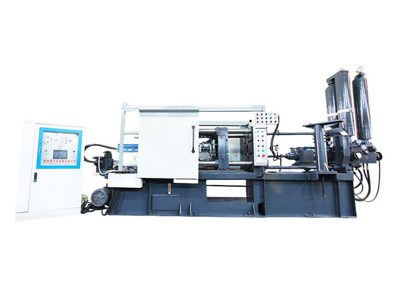
The fundamental architecture of the machine dictates how you set up the process. Hot chamber systems submerge the injection mechanism directly into the molten magnesium bath. This design keeps the metal at a constant temperature right up to the nozzle. Hot chamber machines excel at producing smaller, complex mechanical parts. They offer faster cycle times because there is no separate ladling step. Furthermore, the submerged system provides a lower oxidation risk since the metal remains shielded from the ambient atmosphere.
Conversely, you must specify a magnesium cold chamber die casting machine for larger components. When producing large automotive structural and closure panels, cold chamber systems provide the necessary shot volume and clamping force. Using large structural castings reduces process steps, materials usage, and parts count on the assembly line. Cold chamber machines utilize a separate holding furnace and a ladling system to pour metal into a horizontal shot sleeve.
The ladling process in a cold chamber setup introduces a temperature drop. The metal loses heat as it travels from the furnace to the shot sleeve, and again as it rests in the sleeve before injection. To counter this, operators must run the holding furnace slightly hotter and minimize the delay time between pouring and injection. The shot sleeve itself often requires a dedicated thermal control circuit to prevent the metal from chilling too rapidly before the plunger advances.
Parameter adjustments vary heavily by machine type. In a hot chamber machine, injection speed is limited by the gooseneck hydraulics, and pressure is generally lower. The gooseneck and piston rings wear out over time, leading to internal pressure leaks. Operators must monitor the injection trace for pressure drops, which indicate that the rings need replacement. In a cold chamber machine, you have a much larger hydraulic accumulator driving the plunger, allowing for massive injection speeds and extreme intensification pressures.
Metal dosing settings also differ. Cold chamber systems require precise ladling control to ensure consistent biscuit thickness. A biscuit that is too thick wastes metal and alters the plunger's final position, throwing off the intensification timing. A biscuit that is too thin risks the plunger striking the die block. Hot chamber systems rely on the plunger stroke to determine shot volume, making dosing inherently more consistent but limiting the maximum part size.
Operational Parameter Comparison
Parameter | Hot Chamber System | Cold Chamber System |
|---|---|---|
Typical Cycle Time | Fast (often under 15 seconds) | Slower (30 to 90+ seconds) |
Specific Injection Pressure | 30 MPa to 60 MPa | Up to 100 MPa |
Part Size Suitability | Small to Medium (under 2 kg) | Large Structural (up to 20+ kg) |
Oxidation Risk During Shot | Low (Submerged mechanism) | Higher (Exposed in shot sleeve) |
Metal Delivery Method | Gooseneck and Piston | Automatic Ladle or Dosing Pump |
Maintenance Focus | Gooseneck rings and nozzle heaters | Shot sleeve wear and ladle alignment |
Die lubrication settings directly impact casting quality and tool life. The industry is moving rapidly toward micro-spraying or minimum quantity lubrication (MQL). Traditional heavy water-based sprays cause rapid die cooling. This thermal shock leads to heat checking on the die surface. Furthermore, excess water remaining in the cavity vaporizes upon contact with molten magnesium, causing severe water-induced gas porosity. MQL uses a highly concentrated lubricant applied in tiny volumes, relying on air pressure to distribute the film. This method maintains the die temperature and eliminates water-related defects.
Release agent chemistry is highly specific for magnesium. The lubricant must operate effectively at high die temperatures (200°C to 300°C) without breaking down or building up on the tool surface. Furthermore, the chemistry must not compromise subsequent surface treatments. Heavy wax-based lubricants can leave a residue that prevents powder coating or plating from adhering properly. You must select a magnesium-compatible release agent and tune the spray time to the absolute minimum required for part ejection.
Setting up the spray manifold requires attention to detail. Position the nozzles to target the hottest areas of the die, typically near the gate and thickest cross-sections. Adjust the atomization air pressure to ensure the lubricant forms a fine mist rather than heavy droplets. Run a series of test shots, gradually reducing the spray duration until you observe slight sticking, then increase the time by a fraction of a second to establish the optimal baseline.
Managing air inside the die cavity is a constant battle. Integrating a vacuum system allows you to evacuate air before the metal fills the cavity. Vacuum system integration requires precise timing. The controller must trigger the vacuum valve to open during the slow shot phase and close milliseconds before the molten metal reaches the vent block. Proper vacuum application allows for slightly lower injection pressures and significantly reduces gas porosity in the final part.
Even with vacuum assist, passive venting remains critical. Venting ratios follow a strict mathematical relationship between injection speed, cavity volume, and required vent area. If the vent area is too small for the injection speed, air compresses rapidly inside the cavity. This compression causes the diesel effect, where the air ignites and burns the casting surface. Inadequate venting also creates back-pressure, which resists metal flow and causes misruns. You must calculate the vent area to allow air to escape faster than the incoming metal displaces it.
Chill blocks are a necessary component of the venting system. These corrugated steel blocks allow air to pass through while freezing the molten metal before it can exit the die and enter the vacuum lines. Operators must clean the chill block profiles daily. A clogged chill block restricts airflow, completely negating the benefits of the vacuum system and leading to a sudden spike in porosity defects.
Magnesium is highly reactive. Managing oxidation and fire risks is the highest safety priority in magnesium alloy die casting production. Molten magnesium will ignite if exposed to ambient oxygen. You must utilize protective cover gases in the melting and holding furnaces. Historically, sulfur hexafluoride (SF6) was the standard cover gas. However, due to its extreme global warming potential, the industry has shifted to alternatives like sulfur dioxide (SO2) or HFC-134a. These gases require precise metering and mixing panels to maintain a protective layer over the melt surface without causing equipment corrosion.
Handling protocols for post-processing require strict safety parameters. The casting process generates combustible magnesium swarf, dust, and flash. Downstream operations like trimming the sprue, machining, and sandblasting create fine particulate matter. This dust is highly explosive. Facilities must install specialized wet dust collection systems to capture airborne particles immediately. Operators must store magnesium scrap in designated, dry, non-combustible containers. Standard fire extinguishers are useless against magnesium fires; you must have Class D fire extinguishing agents readily available at all workstations.
Furnace maintenance is a daily requirement. Operators must skim the dross from the surface of the holding furnace carefully. Disturbing the cover gas layer too aggressively exposes the molten metal to air, causing immediate burning. Ensure the mixing panel delivers the exact concentration of SO2 required. Too little gas leads to oxidation, while too much gas accelerates the corrosion of the furnace crucible and surrounding steel structures.
Die steel degrades rapidly under the harsh conditions of magnesium casting. Thermal fatigue, commonly known as heat checking, is the primary failure mode. Heat checking occurs when the die surface expands during metal injection and contracts during spray cooling. Improper temperature settings and aggressive spray cooling cycles accelerate this expansion and contraction cycle, causing microscopic cracks to form on the die surface. Over time, these cracks propagate, leaving raised veins on the cast parts.
Mitigation requires a proactive approach. You must establish a preventative maintenance schedule based on shot count and thermal cycling data. Do not wait for the die to fail. Implement a stress-relieving protocol where the die is removed from the machine and heat-treated at specific shot intervals. Maintain continuous flow in the hot oil or pressurized water heating systems to minimize thermal gradients across the die block. Consistent thermal management is the only way to protect your tooling investment.
Water quality in the cooling circuits also plays a role in die life. Hard water causes scale buildup inside the cooling channels. This scale acts as an insulator, preventing the die steel from transferring heat to the water. As the die runs hotter than intended, soldering occurs, and the thermal fatigue cycle accelerates. Implement a water treatment system to maintain clean cooling channels and ensure consistent heat transfer throughout the life of the tool.
Conduct a comprehensive tooling flow simulation using software to optimize gate design and verify fill time calculations before cutting steel.
Run a pilot test with the shortlisted machine manufacturer using your specific magnesium alloy to validate parameter assumptions and hydraulic response times.
Audit your facility's safety protocols and ventilation systems to ensure compliance with combustible dust regulations prior to handling magnesium swarf.
Establish a strict preventative maintenance baseline for all thermal management systems, including hot oil units and die cooling channels.
A: Ideal injection speeds for magnesium are exceptionally high due to its low latent heat. Plunger velocities often need to exceed 5 to 8 meters per second in the cavity to ensure the metal fills thin-walled sections completely before freezing.
A: Choose a cold chamber machine when producing large, heavy components like automotive structural and closure panels. Cold chamber systems provide the higher shot volumes and massive clamping forces required for large parts, whereas hot chamber machines are limited to smaller components.
A: Magnesium requires significantly faster injection speeds and shorter fill times (often under 20 milliseconds) compared to aluminum. Additionally, the intensification pressure rise time must be much faster because magnesium gates freeze quicker than aluminum gates.
A: Porosity is primarily caused by entrapped air during the injection phase, vaporization of excess water-based die lubricants, or inadequate intensification pressure failing to feed metal shrinkage as the part cools.
A: The required melt temperature depends on the specific alloy, but for common alloys like AZ91D and AM60B, the holding furnace is typically maintained between 630°C and 680°C to ensure optimal flow and minimize oxidation.
A: You prevent oxidation by utilizing precisely metered protective cover gases, such as SO2 or HFC-134a, over the molten metal in the furnace. Additionally, strict housekeeping and wet dust collection systems are required to manage combustible magnesium dust.
A: Magnesium solidifies rapidly. If the intensification pressure rise time exceeds 20 milliseconds, the gate will freeze solid. Once frozen, pressure cannot reach the cavity to feed shrinkage, resulting in internal porosity and weak components.
