
EMAIL:
lh@longhuamachine.com
TELL/whatsapp:
+8619305527239  English English
Views: 0 Author: Site Editor Publish Time: 2026-08-04 Origin: Site


High-volume die casting of high-melting-point alloys frequently suffers from margin-eroding scrap rates due to thermal instability, inconsistent injection profiles, and improper mechanical calibration. Procuring a cold chamber die casting machine is only the baseline. Achieving repeatable, stable production requires precise calibration of the injection system, thermal management, mechanical clamping systems, and alloy-specific tooling configurations. Operators must move beyond basic factory settings and engineer a process tailored to the specific thermodynamic and fluid dynamic requirements of the casting. This guide details the technical setup parameters, evaluation criteria, and risk mitigation strategies required to stabilize production, reduce porosity, and maximize Overall Equipment Effectiveness (OEE) in cold chamber die casting operations.
Stable production relies on the exact synchronization of plunger speed, intensification pressure, and metal pouring temperature.
Setup parameters must be strictly tailored to the alloy; an aluminum cold chamber die casting machine requires different thermal, fill-ratio, and ladling configurations than a magnesium cold chamber die casting machine.
Evaluating machine performance requires analyzing the PQ2 diagram, shot sleeve fill ratio, and the transition time between the filling phase and the intensification phase to minimize gas entrapment and shrinkage porosity.
Proactive calibration of tie-bar tension, accumulator nitrogen pre-charge, and plunger alignment is critical to maintaining long-term dimensional accuracy and reducing unplanned downtime.
Metrics for evaluating production stability include target cycle times, acceptable scrap percentages, and planned maintenance intervals. Establishing a baseline OEE provides a clear benchmark for continuous improvement. Operators must track machine uptime, performance efficiency, and first-pass yield to identify bottlenecks in the casting cycle. Consistent monitoring allows for data-driven adjustments rather than reactive troubleshooting. You need to measure the actual performance against the theoretical maximum of the equipment. A well-calibrated setup minimizes micro-stops caused by stuck parts or minor flash, which silently destroy shift efficiency.
OEE Component | Measurement Focus | Common Cold Chamber Issues |
|---|---|---|
Availability | Planned vs. Actual Run Time | Die changes, plunger tip replacement, furnace charging delays. |
Performance | Ideal Cycle Time vs. Actual Cycle Time | Extended cooling times, slow ladling, sluggish hydraulic response. |
Quality | Good Parts vs. Total Parts Cast | Porosity, cold shuts, dimensional warping, soldering defects. |
Calculating the required locking force depends on the projected casting area, runner system, and intensification pressure. This calculation prevents flash and dimensional non-compliance. If the injection force exceeds the clamping force, the die halves will separate, causing metal to spit and dimensions to swell. You must calculate the total projected area, including all overflows and biscuits, and multiply it by the peak cavity pressure.
Calculate total projected area of the shot.
Determine maximum intensification pressure required for the specific alloy.
Multiply area by pressure to find the theoretical separating force.
Add a 15% to 20% safety margin to account for dynamic pressure spikes.
Set the machine tonnage accordingly.
Calibrating tie-bar strain sensors ensures an even distribution of clamping forces across the die face. This prevents mold deflection and uneven tool wear, which are common causes of premature die failure and out-of-tolerance parts. Uneven tie-bar stretch leads to flashing on one side of the tool and crushing on the other.
Utilizing PQ2 calculations matches the specific hydraulic capability of the machine with the die's gate design. This alignment optimizes cavity filling by balancing available machine power against the resistance of the gating system. A properly matched PQ2 diagram ensures that the metal reaches the extremities of the mold before solidification begins. You plot the machine's performance line against the die's requirement line. The intersection dictates the operating point. If the intersection falls outside the acceptable fill time window, you must alter the gate area or adjust the machine's hydraulic settings.
Closed-loop control systems play a critical role in monitoring and adjusting injection parameters in real-time. These systems maintain shot-to-shot consistency by automatically compensating for minor variations in hydraulic fluid temperature or metal viscosity. Reliable process repeatability is the foundation of low scrap rates and stable high-volume production runs. When the hydraulic oil heats up during a shift, its viscosity drops, which can alter plunger speeds. Closed-loop servo valves detect this deviation within milliseconds and adjust flow rates to maintain the programmed velocity profile.
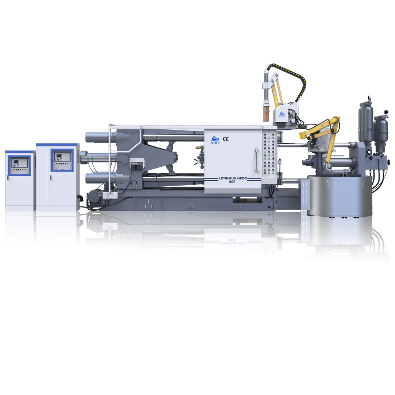
Managing the high latent heat of aluminum alloys requires precise multi-zone die temperature control units (TCUs) and targeted cooling channel design. An aluminum cold chamber die casting machine operates with metal temperatures typically between 650°C and 700°C. This massive thermal load must be extracted rapidly but uniformly to prevent heat checking in the die steel.
Calculating the optimal shot sleeve fill ratio, typically between 30% and 50%, prevents cold flakes and minimizes air entrapment during the slow shot phase. If the sleeve is less than 30% full, the air volume is too high, and the slow shot will likely fold air into the molten metal. Automating the ladling process ensures consistent shot volume and minimizes temperature drops between the holding furnace and the shot sleeve. Selecting and applying appropriate boundary lubricants prevents aluminum soldering and extends the life of the shot sleeve.
Implementing cover gas systems, such as SF6 alternatives, SO2, or CO2 mixtures, over the holding furnace and dosing systems prevents magnesium ignition and oxide inclusions. Magnesium reacts violently with oxygen. A magnesium cold chamber die casting machine must be equipped with specialized dosing furnaces that maintain a protective atmosphere right up to the pour hole.
Accommodating the lower heat capacity and rapid solidification rate of magnesium requires configuring ultra-high-speed injection profiles, often exceeding 6 m/s. Magnesium freezes extremely fast. Integrating high-vacuum venting systems, like chill vents or valve systems, evacuates air from the cavity prior to injection. Adjusting thermal expansion tolerances in the die and shot sleeve specifically for magnesium's thermodynamic properties prevents plunger binding. The clearances between the plunger tip and the sleeve must account for the specific operating temperatures of magnesium casting, which differ significantly from aluminum.
Parameter | Aluminum Setup | Magnesium Setup |
|---|---|---|
Injection Speed | Moderate to High (2-5 m/s) | Ultra-High (5-8+ m/s) |
Melt Protection | Standard fluxing/degassing | Strict cover gas (SF6/SO2) required |
Die Temperature | 200°C - 300°C | 250°C - 350°C |
Fill Time | 20 - 60 milliseconds | 10 - 30 milliseconds |
Setting the initial plunger velocity during the slow approach phase pushes metal past the pour hole without creating a wave that folds over and entraps air. This is Phase 1. The goal is to gather the metal into a solid mass against the plunger face. Calculating the optimal gate velocity during the cavity fill phase (Phase 2) ensures complete mold filling before premature solidification occurs. You must push the metal through the gate fast enough to atomize it, filling the cavity uniformly.
Evaluating the machine's hydraulic response time during the critical switch from velocity control to pressure control dictates the final density of the casting. If the machine hesitates at the end of cavity fill, the metal will freeze before intensification pressure can be applied, resulting in shrinkage porosity.
Applying high terminal squeeze pressure feeds shrinkage during solidification and compresses entrapped gases. This is Phase 3. Setting and maintaining correct nitrogen pressure in hydraulic accumulators ensures instantaneous pressure rise times, typically under 20-30 milliseconds. If the nitrogen pre-charge is too low, the accumulator bottoms out, and you lose squeeze pressure. Utilizing accumulator shock valves and proportional throttle valves minimizes pressure spikes that cause die flashing and premature tool wear. You want a sharp rise in pressure, but not a destructive hydraulic hammer effect.
Designing conformal cooling or targeted water lines manages hot spots in thick-walled sections of the casting. Heavy bosses and thick ribs retain heat longer than thin walls. If these areas are not cooled aggressively, they will suffer from severe shrinkage porosity. Monitoring water flow rates and temperature differentials maintains a steady-state thermal gradient across the die face. You need to measure the Delta-T (temperature difference) between the water entering and leaving the die. A low Delta-T indicates poor heat transfer, possibly due to scaled-up cooling lines.
Using automated IR thermal imaging cameras to inspect die face temperatures after part ejection ensures the cooling cycle runs within established tolerances. Handheld pyrometers are insufficient for complex dies. Fixed IR cameras can trigger an alarm if a specific core pin overheats, allowing the operator to intervene before the pin solders or breaks.
Configuring automated spray manifolds provides consistent, repeatable application of die release agents. Manual spraying introduces massive thermal variations. Balancing the need for adequate lubrication and part release against the risk of over-cooling the die surface is essential. Excess moisture from over-application can cause severe gas porosity in the final casting. The spray should atomize finely, coating the die with a microscopic layer of release agent while the carrier water evaporates instantly upon contact with the hot steel.
Misalignment between the plunger and shot sleeve leads to premature wear, loss of injection pressure, and inconsistent shot volumes. If the shot end sags, the plunger tip will drag on the bottom of the sleeve, causing galling and allowing metal to blow back past the tip. Implementing strict preventative maintenance schedules for alignment checks mitigates this risk. Utilizing high-grade H13 steel or ceramic-coated sleeves, along with optimizing tip cooling systems, significantly extends component lifespan. The cooling water flow to the plunger tip must be verified daily; a blocked tip cooling line will destroy a beryllium copper tip in hours.
Variations in metal temperature cause inconsistent flow characteristics, leading to cold shuts or excessive shrinkage porosity. If the metal is too cold, it will not fill thin sections. If it is too hot, it increases the thermal load on the die and exacerbates soldering. Utilizing advanced thermocouple placement in the holding furnace provides accurate temperature readings. Insulating the transfer ladle and minimizing the delay between pouring and injection stabilizes the thermal profile of the molten metal. The time from the ladle pouring metal into the sleeve to the start of the shot must be absolutely consistent.
Conduct a comprehensive audit of current scrap data to identify whether defects are injection-driven or thermally driven.
Consult with tooling engineers to optimize die design, gating, and cooling layouts for your specific machine capabilities.
Establish a strict preventative maintenance schedule for tie-bar alignment checks and accumulator nitrogen calibration.
Implement automated thermal monitoring using IR cameras to eliminate manual temperature checking inconsistencies.
A: Hot chamber machines have the injection mechanism submerged in molten metal, suitable for low-melting-point alloys like zinc. Cold chamber machines require molten metal to be ladled into a separate shot sleeve, necessary for high-melting-point alloys like aluminum and brass to prevent rapid degradation of machine components.
A: Locking force is calculated by multiplying the total projected area of the casting (including runners and overflows) by the maximum intensification pressure applied during the final phase of injection, plus a safety factor of 10-20% to prevent flashing.
A: The ideal fill ratio typically ranges between 30% and 50%. If the ratio is too low, excessive air remains in the sleeve, causing severe air entrainment during the shot. If it is too high, the liquid metal can spill out or freeze prematurely in the sleeve.
A: A delayed transition from the filling phase to the intensification phase allows the metal to begin solidifying before full pressure is applied, resulting in shrinkage porosity and incomplete filling of thin-walled sections.
A: While the base machine can theoretically handle both, casting magnesium requires significant modifications, including specialized cover gas systems to prevent fires, vacuum-assisted venting setups, different shot sleeve clearances, and faster injection capabilities due to magnesium's rapid cooling rate.
A: Soldering occurs when molten aluminum chemically reacts with the H13 steel of the die. It is typically caused by inadequate die lubrication, excessive metal temperature, or localized hot spots due to poor cooling line placement.
A: Replacement intervals depend heavily on production volume, alloy type, and lubrication practices. Typically, plunger tips require replacement every few thousand shots, while shot sleeves can last tens of thousands of shots if properly aligned and maintained.
