
EMAIL:
lh@longhuamachine.com
TELL/whatsapp:
+8619305527239  English English
Views: 0 Author: Site Editor Publish Time: 2026-08-23 Origin: Site


The injection system in a horizontal die casting machine acts as the primary functional unit determining casting density, surface finish, and scrap rates in high-pressure metal casting. When you force molten metal into a complex steel die at extreme velocities, the mechanical arrangement controlling that metal dictates the success of the production run. Poorly configured injection systems cause air entrapment, premature tool wear, and inconsistent part quality. These issues directly impact foundry profitability and production scalability. To achieve repeatable, high-integrity castings, operators must master the structural arrangement of the injection system. This parallel-to-ground configuration serves as the main variable in controlling molten metal velocity and pressure. By understanding how the shot sleeve, plunger, and hydraulic accumulators interact, engineering teams can accurately evaluate equipment capabilities. This guide breaks down the mechanical setup of horizontal injection systems, providing the criteria needed to specify machinery for demanding production requirements.
System Architecture: The injection system in a horizontal die casting machine is aligned parallel to the ground, utilizing a shot sleeve, injection piston (plunger), and hydraulic intensification system to force molten metal into the die cavity.
Alloy Suitability: The cold chamber horizontal die casting machine configuration is mandatory for high-melting-point non-ferrous alloys like aluminum, brass, and magnesium, preventing rapid degradation of the injection components.
Process Control: Modern evaluation relies on the system's ability to execute a precise three-phase injection process (slow approach, fast fill, intensification) with minimal pressure drop.
System Synchronization: Equipment selection must balance high-speed injection capabilities with the machine's clamping system tonnage to prevent die flash, alongside operational realities of thermal management and maintenance.
To evaluate a machine's capability, buyers must first understand the baseline mechanical arrangement and how the subsystems interact under extreme pressure. The horizontal injection unit is a complex assembly of metallurgical and hydraulic components designed to withstand severe thermal shock and mechanical stress while delivering precise volumetric control. We look at the injection unit not just as a pump, but as a highly calibrated metal delivery mechanism.
The shot sleeve is a heavy-walled cylindrical tube oriented parallel to the factory floor. It rigidly connects to the stationary die half, acting as the primary conduit for molten metal entering the mold. Inside this sleeve operates the injection piston, commonly referred to as the plunger. The plunger assembly consists of a water-cooled rod and a specialized tip that advances the molten metal through the major chamber and into the die runner system.
Because these components endure direct contact with liquefied non-ferrous metals, material selection dictates their lifespan. Shot sleeves are typically forged from premium H13 tool steel and subjected to advanced heat treatments, often nitrided to achieve a surface hardness of 48-52 HRC. This hardness resists thermal fatigue and erosion from the molten alloy. The plunger tip, often machined from beryllium copper or specialized steel alloys, must maintain a precise tolerance against the sleeve wall. If the clearance gap—typically between 0.08mm and 0.12mm depending on the diameter—is too tight, thermal expansion causes galling and seizure. If the gap is too loose, molten metal flashes past the tip, destroying the vacuum and damaging the rod.
Proper installation of the plunger and shot sleeve requires strict adherence to mechanical alignment procedures to prevent premature wear:
Clean the mounting bore on the stationary platen to remove any residual aluminum flash or debris.
Insert the cold shot sleeve into the platen, ensuring the pouring hole is perfectly aligned with the vertical axis (12 o'clock position).
Secure the sleeve using the designated retaining rings, torquing the bolts to the manufacturer's specified limit.
Thread the plunger tip onto the water-cooled rod, applying a high-temperature anti-seize compound to the threads.
Align the plunger rod with the injection cylinder coupling and secure the connection.
Manually advance the injection cylinder at low pressure to verify the tip travels smoothly through the entire length of the sleeve without binding.
Connect and pressure-test the internal water cooling lines to the plunger rod before introducing molten metal.
The mechanical force required to move the plunger at high speeds comes from a dedicated hydraulic power unit. The injection cylinder houses a hydraulic piston connected directly to the plunger rod. Standard hydraulic pumps cannot deliver fluid fast enough to achieve the required metal injection velocities, which often exceed several meters per second. The system needs a massive, instantaneous release of energy.
This deficit is solved by nitrogen-charged accumulators. These heavy-duty pressure vessels store hydraulic fluid under high gas pressure. When the injection valve opens, the compressed nitrogen expands instantly, driving the hydraulic fluid into the injection cylinder with explosive speed. The accumulator system provides the kinetic energy required for the fast-filling phase and the massive static pressure needed for final intensification.
Accumulator Configuration Comparison
Accumulator Type | Mechanism | Response Time | Typical Application |
|---|---|---|---|
Piston Accumulator | A floating metal piston separates the nitrogen gas from the hydraulic fluid. | Moderate (subject to piston friction and inertia). | Main injection force and general intensification in standard machines. |
Bladder Accumulator | A flexible rubber bladder contains the nitrogen gas within the fluid chamber. | Extremely fast (no mechanical friction). | High-speed fast fill phases and rapid pressure spike capture. |
Multi-Stage System | Combines piston and bladder accumulators on a single injection block. | Variable and highly controlled. | Complex structural castings requiring precise phase transitions. |
Located on the top surface of the horizontal shot sleeve, just ahead of the plunger's fully retracted position, is the pouring hole. This opening allows molten metal to be introduced into the chamber prior to the shot cycle. The geometry and placement of this hole are engineered to facilitate rapid pouring while preventing metal from splashing out during the initial plunger movement.
Metal transfer involves ladling the liquefied alloy into the sleeve. This process demands precise volumetric calculation. The volume of metal poured must exactly match the volume of the die cavity, the runner system, the overflows, and a residual "biscuit" that remains in the sleeve. The fill ratio—the percentage of the sleeve's internal volume occupied by the poured metal—typically ranges from 30% to 60%. Inaccurate ladling leads to incomplete fills or excessively thick biscuits. A standard biscuit thickness should be maintained between 15mm and 25mm to ensure proper pressure transmission during the intensification phase.
Differentiating between the two primary die casting methods establishes why the horizontal arrangement is typically associated with specific operational profiles and non-ferrous metals. The fundamental difference lies in how the injection system interacts with the melting furnace.
A cold chamber horizontal die casting machine completely separates the melting furnace from the injection unit. In contrast to hot chamber systems, where the injection mechanism is permanently submerged in a vat of molten metal, the cold chamber system requires metal to be transferred into the machine for every single cycle.
This separation is a physical necessity when working with certain alloys. The molten metal must be precisely calculated and ladled into the major chamber just moments before the plunger advances. By keeping the injection components outside the furnace, the machine avoids continuous exposure to extreme temperatures. This disconnected arrangement prevents the high-temperature molten metal from chemically attacking and dissolving the machine's internal hydraulic and mechanical components. The cycle time is inherently slightly longer than a hot chamber process due to the separate ladling step, but it is the only viable method for high-temperature casting.
Casting aluminum presents specific metallurgical challenges. Aluminum has a relatively high melting point, typically poured around 650°C to 700°C, and a strong chemical affinity for iron. If an aluminum alloy were processed in a hot chamber machine, the molten aluminum would rapidly dissolve the submerged steel injection components, destroying the machine from the inside out through a process known as soldering.
Consequently, the cold chamber horizontal arrangement is the undisputed industry standard for an aluminum horizontal die casting machine. The horizontal layout allows for efficient, gravity-assisted ladling and straightforward integration with automated ladling robots. Successfully filling aluminum molds before the metal undergoes premature solidification requires massive injection pressure and extreme speed. The horizontal cold chamber design accommodates the heavy-duty hydraulic accumulators necessary to generate these forces, ensuring the aluminum reaches the furthest extremities of the die cavity while still in a fully liquid state.
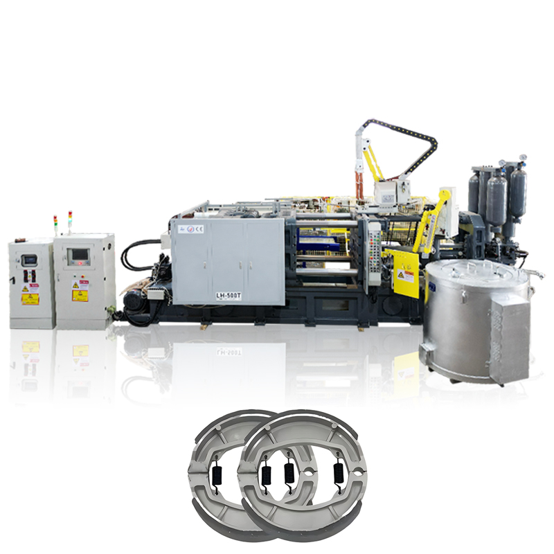
Mapping the mechanical movement of the injection system to the physical outcomes of the cast part reveals the complexity of high-pressure die casting. The injection cycle is not a single, uniform push. It is a highly controlled, three-phase sequence designed to manage fluid dynamics and phase changes. Operators must program the machine to execute these phases with millisecond precision.
The cycle begins with the slow approach. Once the metal is poured into the sleeve, the injection piston moves forward at a controlled, relatively low velocity, typically between 0.15 and 0.35 meters per second. The plunger passes the pouring hole, sealing the chamber.
The objective of this phase is to move the resting metal into the runner system smoothly. The plunger must push the air out of the shot sleeve and die cavity ahead of the metal front. If the plunger moves too fast, the metal will roll over itself, creating turbulence and folding air into the molten mass. This trapped air results in severe internal porosity. The slow shot velocity must be calculated to create a single, rolling wave of metal that pushes gases toward the die vents without breaking the surface tension. The transition point from Phase 1 to Phase 2 occurs exactly when the molten metal reaches the ingate.
Once the molten metal reaches the ingate, the system triggers Phase 2. The hydraulic accumulator discharges, causing a rapid acceleration of the plunger. The liquefied metal is violently injected into the die cavity under high pressure. Plunger velocities during this phase can range from 2 to 8 meters per second, translating to gate velocities of 30 to 60 meters per second.
This extreme velocity is necessary to atomize the metal slightly and force it into complex geometries and thin wall sections before the alloy freezes against the cold steel of the die. The entire cavity fill time often lasts only 10 to 40 milliseconds. Inadequate fast-shot speed leads to cold shuts, where two fronts of cooling metal meet but fail to fuse, resulting in a structurally compromised part with visible surface defects.
As the die cavity fills completely, the forward movement of the plunger abruptly stops. At this exact millisecond, Phase 3 begins with the sudden application of high static pressure at the end of the stroke. A secondary intensification valve opens, routing maximum hydraulic pressure to the injection cylinder. This pressure often reaches 500 to 1200 bar on the metal.
This intensification phase compacts the metal as it begins to solidify. The massive pressure serves two purposes: it crushes any residual trapped gases into microscopic, structurally insignificant pores, and it feeds additional molten metal from the biscuit into the cavity to compensate for volumetric shrinkage. Without adequate intensification, the final casting will suffer from shrinkage porosity and dimensional instability. The pressure must be held until the gate freezes completely.
Injection Defect Troubleshooting
Defect Type | Visual Indicator | Injection Phase Root Cause | Corrective Action |
|---|---|---|---|
Gas Porosity | Smooth, round internal voids visible on X-ray or after machining. | Phase 1 velocity too high, causing wave turbulence and trapped air. | Reduce slow shot speed; verify fill ratio; check die venting. |
Cold Shuts | Distinct lines or cracks where metal flows failed to merge. | Phase 2 velocity too low, causing premature metal freezing. | Increase fast shot speed; raise metal pouring temperature. |
Shrinkage Porosity | Irregular, jagged internal voids, often in thick wall sections. | Phase 3 intensification pressure too low or applied too late. | Increase intensification pressure; check accumulator nitrogen charge. |
Die Flash | Excess metal escaping the parting line of the mold. | Phase 3 pressure exceeds machine clamping force. | Reduce intensification pressure; verify clamping tonnage setup. |
Procurement and engineering teams must assess different machine models based on their injection capabilities and how those systems integrate with the rest of the machine. An injection unit cannot be evaluated in isolation; its performance is tied directly to the machine's overall architecture. You must look at the hydraulic circuit, the control software, and the physical layout.
The relationship between the metal-injection system and the clamping system is a fundamental physics equation. The intensification pressure generated by the injection unit applies outward force against the die halves. This force must be adequately countered by the machine's locking tonnage.
When selecting a horizontal die casting machine, engineers calculate the projected area of the casting, including the runner and overflows, and multiply it by the specific injection pressure. If the injection force exceeds the clamping force, the die halves will separate slightly during Phase 3. This separation causes molten metal to spit out of the parting line, creating dangerous and wasteful die flash. High-pressure injection capabilities are useless if the machine lacks the rigid toggle mechanism and tie bar strength to hold the mold completely shut.
A machine's ability to maintain consistent pressure correlates directly with accumulator sizing and hydraulic valve response times. During the transition from Phase 2 to Phase 3, there is a natural tendency for hydraulic pressure to drop as the fluid changes direction and valves shift. This is often analyzed using a PQ2 diagram, which maps pressure against flow rate.
Evaluating this pressure drop is mandatory. If the pressure sags for even a few milliseconds, the metal in the ingate may freeze, blocking the intensification pressure from reaching the cavity. High-end machines utilize oversized accumulators positioned as close to the injection cylinder as possible, paired with ultra-fast cartridge valves, to ensure a seamless, instantaneous transition from velocity to pressure.
The method of controlling the hydraulic valves defines the machine's technological tier. Open-loop systems rely on pre-set valve openings. If the hydraulic oil heats up and thins out, or if the plunger tip wears down and increases friction, an open-loop system cannot detect or correct the resulting changes in shot speed.
Modern closed-loop systems use linear transducers and pressure sensors to monitor the plunger's exact position and velocity thousands of times per second. The control software compares this real-time data against the programmed shot profile. If it detects a deviation, it adjusts the servo-proportional valves in milliseconds using advanced PID control loops. This closed-loop architecture ensures repeatable shot profiles regardless of minor temperature fluctuations, viscosity changes, or mechanical wear.
The physical arrangement of the injection unit heavily influences operational uptime. Shot sleeves, plunger tips, and piston rings are consumable wear parts that require frequent inspection and replacement. If the machine's structural design obstructs access to the injection area, routine maintenance takes hours instead of minutes.
Evaluating the layout requires looking at the clearance between the rear tie bars and the injection cylinder. Machines that offer ample space for maintenance crews to safely extract a hot shot sleeve or swap a plunger rod reduce labor costs and increase overall equipment effectiveness. The system must be designed for rapid changeovers to keep the foundry running efficiently.
Injection System Preventative Maintenance Schedule
Component | Inspection Frequency | Maintenance Action | Replacement Indicator |
|---|---|---|---|
Plunger Tip | Every Shift (8 hours) | Check for galling, verify cooling water flow, ensure lubrication coverage. | Loss of vacuum, visible scoring on the tip, or metal flashing past the rings. |
Shot Sleeve | Weekly | Measure internal diameter for washout or ovality; check pouring hole edges. | Internal diameter exceeds tolerance by 0.15mm, or severe heat checking occurs. |
Accumulator | Monthly | Verify nitrogen pre-charge pressure using a calibrated gauge. | Nitrogen pressure drops consistently, indicating a ruptured bladder or worn piston seal. |
Hydraulic Fluid | Quarterly | Take fluid samples for particle count and viscosity analysis. | High particulate count or fluid degradation beyond ISO cleanliness standards. |
Operating high-pressure horizontal injection systems involves navigating realistic physical challenges. Foundries must balance aggressive production targets with the limitations of metallurgy and thermodynamics. You cannot push the equipment beyond its physical limits without incurring severe maintenance penalties.
A significant risk in horizontal arrangements is shot sleeve warping. When molten metal is poured into the horizontal sleeve, it rests on the bottom surface before the plunger advances. This creates a severe thermal gradient: the bottom of the sleeve expands rapidly from the heat, while the top remains relatively cool.
This uneven temperature distribution causes the steel sleeve to bow or distort. A warped sleeve binds the plunger tip, causing erratic shot speeds and catastrophic equipment failure. Mitigation strategies include implementing active water-cooling jackets around the sleeve, utilizing advanced thermal regulation units, and enforcing strict, automated plunger lubrication protocols to minimize friction during the stroke. Proper thermal management keeps the sleeve perfectly cylindrical.
The horizontal cold chamber system inherently struggles with air entrapment compared to vertical arrangements where gravity assists in venting. Because the sleeve is only partially filled with metal, a large volume of air sits above the molten pool. Pushing this air out without mixing it into the metal requires precise control.
Mitigation tactics rely on optimizing the Phase 1 slow shot velocity profile to create an ideal wave dynamic. Furthermore, many foundries integrate high-vacuum die casting technology. By drawing a deep vacuum on the die cavity and shot sleeve just before injection, the system mechanically removes the air, drastically reducing porosity and allowing for structural castings that can be heat-treated or welded.
Production managers face a constant trade-off between running the injection system at maximum velocity to increase throughput and preserving the lifespan of hydraulic seals and plunger components. Pushing the machine to its absolute limits accelerates wear on the accumulator seals, increases the frequency of plunger tip replacements, and stresses the die steel.
Calculating optimal operating parameters requires analyzing part geometry and quality requirements. A thick-walled, non-structural part may tolerate slower injection speeds and lower intensification pressures, significantly extending component life. Conversely, thin-walled automotive structural components demand maximum performance, requiring foundries to accept higher maintenance frequencies as a necessary operational trade-off. You must tune the machine to the specific requirements of the casting, not just run it at maximum capacity.
To ensure a successful equipment acquisition and optimize your foundry operations, take the following steps:
Request detailed, real-time shot profile graphs from OEMs to verify closed-loop valve response times and pressure transition stability.
Evaluate accumulator recovery times to ensure the hydraulic system can maintain consistent cycle times without pressure degradation.
Conduct a wear part longevity analysis, factoring in the replacement frequency of plunger tips and shot sleeves based on the intended alloy and production volume.
Assess the physical layout of the injection unit on the factory floor to guarantee maintenance crews have unobstructed access for rapid tooling changes.
Verify the machine's clamping tonnage provides a sufficient safety margin above the calculated injection force to prevent die flash.
A: A hot chamber machine has its injection mechanism submerged directly in the molten metal furnace, suitable for low-melting-point alloys like zinc. A cold chamber machine separates the furnace from the injection unit. Molten metal is ladled into the chamber for each cycle, making it mandatory for high-melting-point non-ferrous alloys like aluminum, which would otherwise dissolve the submerged components.
A: The horizontal arrangement aligns with standard factory floor layouts and simplifies the integration of automated ladling and part extraction robots. It allows for easier access to the die halves for maintenance, spraying, and insert loading. While vertical systems offer some advantages in air evacuation, horizontal systems provide superior overall production efficiency and automation compatibility.
A: The injection system generates massive internal pressure during the final intensification phase to compress the solidifying metal. This pressure pushes outward against the die halves. The clamping system must provide a counteracting locking force greater than the injection force to keep the die completely closed, preventing molten metal from escaping as flash.
A: Plunger tips are manufactured from specialized heat-resistant alloys, such as beryllium copper or H13 tool steel. They are designed with internal cooling channels that circulate water to manage thermal expansion. Additionally, automated lubrication systems apply high-temperature oils or graphite-based lubricants to the tip before every cycle to reduce friction and prevent galling against the sleeve.
A: Pressure drop typically occurs during the transition from the fast-filling phase to the intensification phase. It is caused by hydraulic inefficiencies, undersized accumulators that deplete their stored energy too quickly, or slow-shifting hydraulic valves that fail to redirect fluid fast enough to catch the pressure spike before the metal freezes in the gate.
A: Metal volume is controlled using automated ladling robots or pneumatic dosing furnaces that deliver a precise, pre-calculated amount of molten alloy into the shot sleeve. This calculation accounts for the volume of the part, the runner system, overflows, and the required biscuit thickness. Precise dosing is required to ensure complete mold filling without excessive material waste.
A: The intensification phase applies a massive spike in static pressure at the very end of the injection stroke. This high pressure compresses any residual trapped air or gases into microscopic pores. More importantly, it forces additional liquid metal into the cavity to compensate for the natural volumetric shrinkage that occurs as the alloy cools and solidifies.
