
EMAIL:
lh@longhuamachine.com
TELL/whatsapp:
+8619305527239  English English
Views: 0 Author: Site Editor Publish Time: 2026-08-21 Origin: Site


In high-volume manufacturing, cycle time dictates unit cost, production viability, and overall equipment effectiveness. Evaluators often oversimplify cycle speed by looking only at dry cycle times. They ignore the thermal, mechanical, and geometric variables that cause real-world production bottlenecks and inflate machine time costs. We must establish a framework for evaluating the specific mechanical components, thermal management systems, and operational trade-offs that determine the true cycle speed of a Zinc Die Casting Machine. This approach enables accurate return on investment calculations, targeted cost reduction, and effective vendor shortlisting. By breaking down injection mechanics, cooling infrastructure, and part geometry constraints, manufacturers can optimize their processes. You will learn how to identify hidden cycle delays, balance speed against maintenance costs, and configure your equipment for maximum sustainable output.
The injection phase is the most critical mechanical determinant of cycle speed, requiring precise synchronization of accumulator performance, plunger velocity, and pressure.
Thermal management—specifically die cooling infrastructure and lubrication spray time—often represents the primary bottleneck in achieving theoretical maximum cycle speeds.
Part geometry and ejection complexity directly constrain cycle times; multi-cavity or complex-core molds require slower, controlled ejections to prevent part deformation.
Maximizing cycle speed introduces strict trade-offs with machine maintenance, specifically accelerating wear on hot chamber consumables like goosenecks and rings.
Die casting cycle time is the exact time lapse between the beginning of one injection cycle and the initiation of the next. This measurement serves as the baseline metric for all process optimization efforts on the shop floor. Tracking this duration accurately reveals where mechanical delays or thermal inefficiencies hide. You cannot improve what you do not measure precisely. Operators must look beyond the theoretical dry cycle speed printed on a machine brochure and measure the actual floor-level performance under thermal load.
A single cycle breaks down into a strict chronological sequence. Understanding these phases allows process engineers to target specific areas for time reduction:
Die Closing and Tonnage Build: The moving platen advances to meet the stationary platen. The machine engages its locking mechanism to build the required clamping force, preventing the die from blowing open during injection.
Injection (Fill Time): The plunger descends into the gooseneck, forcing molten zinc through the nozzle, sprue, runners, and gates into the die cavity. This phase happens in milliseconds.
Cooling and Solidification: The molten metal transfers its heat into the die steel. Water or oil flowing through internal cooling channels extracts this heat until the part becomes rigid enough for ejection.
Die Opening: The clamping mechanism releases, and the moving platen retracts. The part shrinks onto the moving half of the die (the ejector half) as it cools.
Ejection: Hydraulic or mechanical ejector pins push forward, stripping the solidified casting off the die cores. The part either falls freely or is removed by a robotic arm.
Die Lubrication and Blow-off: Spray manifolds apply a release agent to the die surfaces. Compressed air blows away excess liquid and debris, preparing the tool for the next shot.
Zinc provides a distinct material advantage for rapid manufacturing. Its low melting point and high thermal conductivity allow parts to cool and solidify in mere seconds. This rapid heat transfer inherently enables faster baseline cycles than aluminum or magnesium alloys. The metal flows easily, fills thin walls rapidly, and freezes quickly, shrinking the longest phase of the casting cycle. Different zinc alloys behave differently under thermal stress. Zamak 3, the most widely used zinc alloy, offers excellent castability and predictable shrinkage, supporting aggressive cycle speeds. Zamak 5 adds copper for higher strength but requires slightly tighter thermal control to prevent hot tearing during rapid ejection.
The fundamental architecture of a hot chamber zinc die casting machine inherently operates at faster cycle speeds than cold chamber alternatives. Hot chamber systems submerge the injection mechanism directly in the molten metal bath. This design eliminates the molten metal ladling phase entirely. The continuous availability of liquid metal at the plunger tip shaves seconds off every single shot. There is no waiting for a ladle to travel from a holding furnace to a shot sleeve. The metal is always ready, kept at the exact casting temperature within the gooseneck.
The injection process acts as the most demanding phase of the cycle. Precise control over timing, speed, and pressure remains non-negotiable for reducing overall cycle time without compromising part density. If the injection is too slow, the metal freezes before filling the cavity, resulting in cold shuts and incomplete fills. If it is too fast without proper venting, trapped air causes internal porosity and surface blisters. Mastering this phase dictates the success of the entire operation.
Hydraulic accumulator capacity and valve response times dictate the millisecond-level precision required for fast fill times. The accumulator stores hydraulic energy in the form of pressurized nitrogen gas, releasing it instantly to drive the injection piston forward. High-performance proportional valves control this release, ensuring the plunger achieves maximum velocity exactly when needed. Sluggish valves add milliseconds to the fill time, which compounds over thousands of cycles. Modern machines utilize closed-loop control systems that monitor plunger position and adjust hydraulic flow in real-time, ensuring consistent fill times regardless of oil temperature fluctuations.
Thin-walled zinc parts demand ultra-fast injection speeds to prevent premature freezing in the cavity. Zinc loses heat rapidly upon contact with the relatively cold die steel. The machine must force the metal through the gates and into the furthest extremities of the mold before the material drops below its liquidus temperature. Robust injection cylinders and optimized hydraulic circuits are mandatory for these high-speed applications. Operators often utilize a two-stage injection profile: a slow approach to push air out of the gooseneck and runners, followed by a high-speed, high-pressure phase to pack the cavity instantly.
An inverse relationship exists between machine size, measured in clamping tonnage, and dry cycle speed. Larger machines require more time to move massive platens and build hydraulic pressure. A 400-ton machine will inherently cycle slower than a 50-ton machine due to the sheer mass of the moving components and the volume of hydraulic oil required to actuate the cylinders. Selecting an oversized machine for a small part artificially inflates your cycle time. Process engineers must match the machine tonnage closely to the projected surface area of the casting to maximize speed.
Mechanical toggle systems and fully hydraulic clamping units offer different speed and lock-up efficiencies. Toggle systems utilize mechanical linkage to multiply force, snapping shut rapidly and locking securely over center. This provides excellent speed for high-volume zinc applications. The mechanical advantage allows a smaller hydraulic cylinder to generate massive clamping force quickly. Direct hydraulic systems offer infinite tonnage adjustment and precise stroke control but often require slightly longer pressure-building phases to achieve full lock-up. For pure speed in zinc casting, toggle machines remain the industry standard.
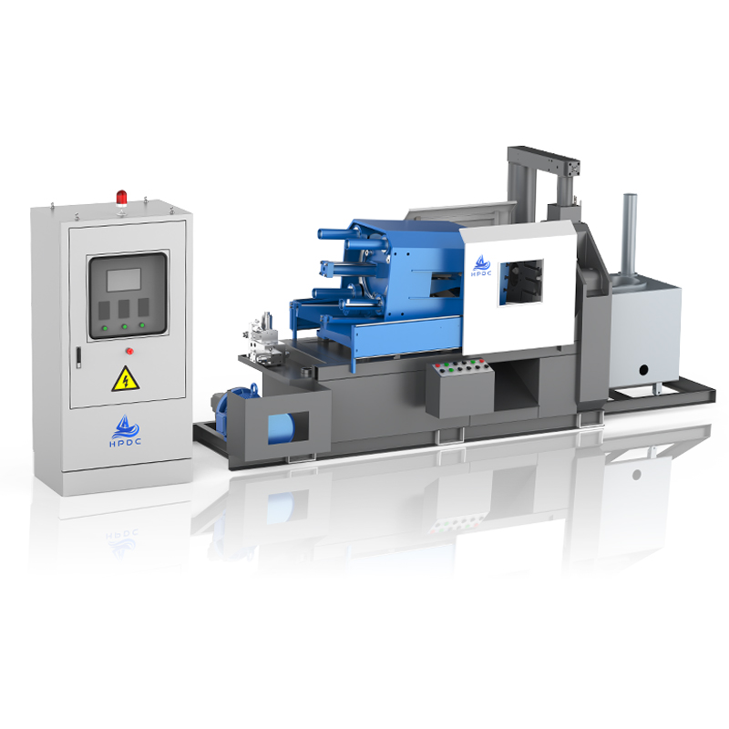
The volume and placement of water or thermal oil cooling lines within the die dictate how rapidly the liquid zinc solidifies. Heat dissipation requirements scale directly with the mass of the cast part and the speed of the cycle. If the cooling infrastructure cannot remove heat faster than the injection phase introduces it, the cycle must slow down to allow the part to freeze. Tooling engineers drill complex networks of cooling channels, bubblers, and baffles deep into the die blocks to extract heat from heavy sections of the casting.
Maintaining a strict die temperature window establishes thermal equilibrium. Cooling the die too fast causes flow marks, cold shuts, and premature freezing during the fill phase. Cooling the die too slowly extends the solidification phase, forcing the machine to wait before opening. Advanced thermal imaging and strategically placed thermocouples help operators dial in the exact water flow rates needed to balance quality and speed. Over time, mineral scale builds up inside water cooling lines, acting as an insulator. This scale severely degrades heat transfer, causing cycle times to creep upward over months of production. Regular descaling maintenance is mandatory to sustain high cycle speeds.
Applying release agents and utilizing air blow-off to clean the die face consumes valuable seconds between shots. The spray phase cools the die surface and prevents the zinc from soldering to the steel. However, excessive spraying wastes time and introduces thermal shock, which accelerates die fatigue and leads to heat checking on the tool surface. Optimizing the spray pattern and duration is a primary target for cycle time reduction. Operators often use custom-built spray manifolds that match the exact cavity layout, applying lubricant only where needed rather than flooding the entire die face.
Minimal quantity lubrication (MQL) and micro-spray systems drastically reduce the thermal shock and time associated with traditional water-based die spraying. These systems apply a highly concentrated, atomized mist of lubricant directly to critical areas. By eliminating the heavy water volume, micro-spray systems cut the spray phase duration to a fraction of a second, significantly boosting overall machine output. MQL relies entirely on the internal cooling lines to manage die temperature, shifting the thermal burden away from the external spray. This transition requires highly optimized internal cooling but yields massive gains in cycle speed.
Typical Cycle Phase Time Distribution and Optimization Strategies
Cycle Phase | Typical Duration (Seconds) | Primary Bottleneck Factors | Optimization Strategy |
|---|---|---|---|
Die Closing & Clamping | 0.5 - 1.5 | Platen mass, toggle kinematics, hydraulic pump capacity | Optimize stroke length; maintain toggle linkage lubrication. |
Injection (Fill Time) | 0.01 - 0.05 | Accumulator pressure, proportional valve response time | Ensure proper nitrogen pre-charge; use closed-loop control. |
Cooling & Solidification | 1.0 - 5.0 | Part wall thickness, die cooling line placement, water flow | Implement conformal cooling; descale water lines regularly. |
Die Opening | 0.5 - 1.5 | Opening stroke length, hydraulic return speed | Set opening stroke to the absolute minimum required for ejection. |
Ejection | 0.2 - 2.0 | Part complexity, draft angles, robotic vs. free-fall extraction | Maximize draft angles; polish cores to reduce friction. |
Die Lubrication (Spray) | 0.5 - 3.0 | Spray manifold design, MQL vs. water-based systems | Transition to micro-spray (MQL) technology. |
Part design limits how quickly a component can be ejected without galling or distortion. Deep draws and minimal draft angles create high friction against the die steel as the part shrinks during cooling. The machine must apply greater ejection force and move the ejector pins slower to push the part off the core without bending it. Generous draft angles allow the part to pop off the tool instantly. Tooling designers must advocate for maximum allowable draft during the part design phase to ensure high-speed manufacturability.
Complex ejection sequences severely impact total cycle time. Scenarios requiring specialized ejection, such as rotating mechanisms for helical gears, demand precise, multi-step movements. The tool must rotate as the part is ejected, acting much like a screw backing out of a thread. Moving cores, side pulls, and hydraulic slides all require sequential activation, adding seconds to the die-open phase. Each mechanical movement must complete and verify via limit switches before the next movement begins. Simplifying part geometry to eliminate side pulls directly translates to faster cycle speeds.
A specialized zinc medal die casting machine focuses on flat, low-complexity, multi-cavity molds. These high-speed, low-weight profiles represent the pinnacle of rapid cycle times. Medals possess uniform wall thickness and minimal deep cores, allowing the zinc to solidify almost instantly. The cooling phase is exceptionally short, and the flat geometry prevents the part from gripping the die steel tightly. Operators can run these machines at near-maximum dry cycle speeds because the thermal and geometric constraints are minimal.
Simple geometries allow for rapid free-fall ejection, minimizing the die-open duration. Once the die parts, the ejector pins strike quickly, and the medals drop directly into a quench tank or conveyor below. This gravity-drop method eliminates the need for a robotic arm to enter the envelope, grip the part, and retract. The machine closes again immediately, maximizing shots per hour. For flat components like medals, zippers, and simple fasteners, gravity ejection combined with a water quench provides the highest possible production rate.
Automated robotic extraction adds seconds to the cycle but ensures part integrity for complex or cosmetic components. The robot must wait for the die to open, move into position, grip the casting, and exit the safety envelope before the machine can close. While slower than gravity-drop methods, robotic extraction prevents parts from denting each other as they fall. For high-end cosmetic parts like automotive interior trim or premium hardware, the time penalty of robotic extraction is a necessary trade-off to maintain surface quality.
Part-verification sensors add micro-delays to the cycle but prevent catastrophic die damage. Infrared scales, vision systems, or laser curtains verify that the part has successfully cleared the die before initiating the next close. If a part sticks to the ejector pins or breaks off in the cavity, the sensor halts the machine, preventing the die from crushing the retained metal. Crushing a solid zinc part between two steel die halves destroys the tool and bends the machine platens. These safety checks cost fractions of a second but save thousands of dollars in tooling repairs and weeks of downtime.
Matching the cycle speed of automated quenching, trimming, and machining cells to the die casting machine prevents downstream bottlenecks. If the trim press cycles slower than the casting machine, parts will accumulate, forcing the primary machine to pause. You must pace the entire work cell to the slowest operation. Upgrading a casting machine for speed yields no benefit if the peripheral equipment cannot keep up. Process engineers must design the entire cell as a single synchronized unit.
Integrating conveyors and cooling tunnels requires careful timing. The parts must reach the trim press at the correct temperature to ensure clean shearing of the gates and runners. If the casting cycle accelerates, the parts may arrive too hot, causing the zinc to smear rather than snap cleanly during trimming. Conversely, if they arrive too cold, the trim die experiences excessive wear and the zinc may crack. Process engineers must balance the primary cycle speed with the thermal requirements of secondary inline operations, adjusting conveyor speeds and cooling fans accordingly.
Running a hot chamber machine at maximum theoretical speed introduces significant implementation risks. Pushing the equipment to its absolute limits accelerates wear on critical hot chamber consumables. The gooseneck, nozzle, and plunger rings endure higher friction and thermal stress. The constant, rapid movement of the plunger through the molten zinc bath wears down the cast iron gooseneck sleeve. The die steel experiences faster thermal cycling, leading to premature heat checking and fatigue cracking on the cavity surface.
Operators must balance slightly slower, stable cycle times against the high costs of unplanned maintenance and tooling fatigue. A machine running at 90% of its maximum speed might run continuously for weeks without issue, producing a predictable yield. Pushing that same machine to 100% might cause a plunger tip failure or a blown nozzle heater every three days. The downtime required to cool the machine, replace broken components, and bring the system back up to operating temperature quickly negates the extra parts gained from the faster cycle. Consistency always outperforms erratic bursts of speed.
Calculating the true cost per cycle requires factoring in hydraulic pump energy consumption, furnace holding energy, and operator labor over the duration of the cycle. Every second the machine runs incurs a fixed operational cost. If a cycle takes ten seconds, you divide the hourly machine rate by 360 shots. If you reduce that cycle to eight seconds, you divide the same hourly rate by 450 shots, drastically lowering the cost per unit. This calculation proves why cycle time optimization remains the most direct path to higher profit margins.
Shaving even fractions of a second off the cycle time exponentially reduces the overall machine time cost. Optimizing the die spray duration, increasing the hydraulic return speed, or refining the cooling water flow directly lowers labor, energy, and general maintenance expenses per unit produced. Consistent, incremental improvements in cycle speed yield massive financial returns over high-volume production runs. Process engineers should conduct regular time studies, filming the machine in operation and analyzing the footage frame-by-frame to identify wasted milliseconds in platen movement or robotic extraction.
Cycle speed is not a static machine specification. It is a dynamic output determined by the complex interplay of injection mechanics, thermal management, and part geometry. Achieving maximum output requires looking beyond dry cycle times and addressing the physical realities of molten metal flow, heat dissipation, and mechanical extraction. By optimizing each phase of the cycle, manufacturers can significantly reduce machine time costs and increase overall profitability.
Evaluators should prioritize machines equipped with advanced proportional valve technology and robust cooling capabilities. Selecting equipment based solely on dry cycle time claims leads to inaccurate production forecasting. Focus on the machine's ability to maintain thermal equilibrium and execute precise, repeatable injection profiles under heavy production loads.
Take the following actionable steps to optimize your cycle times:
Conduct mold flow and thermal analysis on your die designs to optimize cooling line placement before cutting steel.
Request empirical cycle time data from OEMs based on the specific die weight and geometry of your intended production parts.
Audit your current die lubrication process and evaluate the return on investment of upgrading to a micro-spray or MQL system.
Implement part-verification sensors to allow for faster, safer gravity-drop ejection where part geometry permits.
Standardize preventative maintenance schedules for goosenecks and plunger rings to sustain high-speed operations without unplanned downtime.
A: Die casting cycle time is the total time lapse between the initiation of one injection cycle and the start of the next. It encompasses die closing, metal injection, cooling and solidification, die opening, part ejection, and die lubrication.
A: Typical cycle times range from 2 to 10 seconds for small to medium parts. Highly optimized setups running simple, flat components can achieve cycles under 3 seconds, while larger, complex parts may require 10 to 15 seconds to properly cool and eject.
A: Wall thickness directly dictates the cooling phase duration. Thicker walls retain more heat, requiring a longer solidification time before the die can open. Designing parts with uniform, thin walls minimizes cooling time and significantly accelerates the overall cycle.
A: Hot chamber machines keep the injection mechanism submerged in the molten zinc bath. This eliminates the need to ladle molten metal into a shot sleeve for every cycle, removing a slow, mechanical step and allowing for rapid, continuous injection.
A: Yes. Traditional water-based spray systems take several seconds to apply and evaporate. Upgrading to minimal quantity lubrication (MQL) or micro-spray technology reduces spray time to fractions of a second and minimizes thermal shock to the die.
A: Higher clamping tonnage requires moving larger, heavier platens and building greater hydraulic pressure. Consequently, larger machines inherently have slower dry cycle times. Using an oversized machine for a small part unnecessarily extends the die closing and opening phases.
