
EMAIL:
lh@longhuamachine.com
TELL/whatsapp:
+8619305527239  English English
Views: 0 Author: Site Editor Publish Time: 2026-08-08 Origin: Site


Tooling modifications cause some of the most expensive and time-consuming delays in manufacturing. A fraction of a degree in tooling design dictates whether you get a seamless production run or catastrophic part distortion. As molten aluminum cools inside a die, it shrinks and grips the steel tooling with immense force. Combined with aluminum’s naturally abrasive properties, inadequate draft leads directly to scuffed surfaces, bent ejector pins, and premature wear on the cavity blocks.
Specifying the correct draft angle during the Design for Manufacturability phase prevents these failures. You cannot rely on the toolmaker to guess your intent. This guide breaks down the exact draft tolerances required to ensure clean part release, protect your tooling investment, and maintain strict dimensional accuracy across high-volume production runs.
Standard Baselines: Most standard aluminum castings require a draft angle of ± 1° to 2° to counteract the metal's abrasive nature and shrinkage rates.
Core vs. Cavity Variances: Internal features (cores) typically require higher draft angles (often 1.5° to 2°) because the aluminum shrinks onto them, while external features (cavities) can often release cleanly with as little as 0.5°.
Process Comparison: While investment casting typically relies on ~1.5° draft and sand casting requires even larger tapers, high-pressure die casting utilizes precision steel molds that can leverage tighter, highly-engineered draft tolerances.
Application Dictates Angle: Deep draws, textured surfaces, and specific end-use applications dictate draft requirements—what works for a simple bracket will fail for a complex thermal enclosure.
Zero-Draft is High-Risk: While "zero draft" is technically possible for very shallow features, it significantly increases tooling wear, cycle times, and the risk of ejection failure.
A clean release on the shop floor means the part ejects with zero surface scuffing, no deformation, minimal stress on the ejector pins, and highly predictable cycle times. Achieving this requires a deep understanding of how aluminum behaves as it transitions from a 650°C molten state to a solid component inside a closed steel die.
Aluminum alloys, such as A380 or A360, typically exhibit a shrinkage rate of 0.4% to 0.6% during solidification. As the metal cools, it constricts tightly around any internal tooling features. Furthermore, solidifying aluminum is highly abrasive against H13 tool steel. Without proper draft, the mechanical friction between the shrinking part and the mold walls causes severe galling, where aluminum physically welds itself to the steel.
Draft creates immediate clearance the exact millisecond the ejector pins actuate. Even a minimal 0.5° taper breaks the vacuum and physical friction instantly, allowing the part to slide out smoothly without distortion. This mechanical clearance is what separates a well-designed Aluminum Die Casting Mold from one that requires constant polishing and maintenance.
When comparing high-pressure die casting to alternative methods, the differences in draft requirements become clear. Sand casting and investment casting often require 1.5° to 3° or more due to the porous or expendable nature of their mold materials. In contrast, the high-pressure environment of die casting relies on hardened precision steel molds. Here, draft precision is critical not just for part release, but to prevent mold micro-cracking caused by excessive ejection forces over hundreds of thousands of shots.
The thermal dynamics inside the die also play a massive role. The die blocks absorb immense heat during the injection phase. If a part lacks draft, the extended contact time during a difficult ejection transfers excess heat into specific areas of the die, leading to thermal fatigue and heat checking. Proper draft ensures the part leaves the die quickly, maintaining a stable thermal equilibrium.
Ejector pin placement must work in tandem with draft angles. You can have a perfectly drafted wall, but if the ejector pins are placed too far from the deep draw features, the part will still warp during ejection. The draft reduces the required force, allowing the pins to push the part evenly off the cores without punching through the semi-solid aluminum.
Applying draft is not a one-size-fits-all process. The specific geometry of the part dictates the exact angle required for a clean release. Engineering teams must evaluate every single wall, boss, and rib independently.
Internal features, known as cores, require larger draft angles. Because aluminum shrinks onto the core as it cools, it grips the steel tightly. A minimum of 2° is generally recommended for deep cores, while 1.5° may suffice for shallow features. If you design a deep cylindrical boss without adequate draft, the aluminum will shrink so tightly around the core pin that it will snap the pin during ejection.
Conversely, external features, or cavities, allow for smaller draft angles. The aluminum shrinks away from the cavity walls, meaning angles as low as 0.5° to 1° can often facilitate a clean release. The metal naturally pulls itself away from the steel, reducing the friction coefficient significantly.
The depth of the draw plays a crucial role in calculating draft. Longer draws require more draft to prevent galling over the extended surface area. A 10mm deep rib might survive with 1° of draft, but a 50mm deep housing wall will require 2° or more to prevent drag marks. Maintaining a constant wall thickness while applying draft ensures uniform cooling and reduces the risk of internal porosity.
Parting line placement directly dictates the draw direction and impacts the net-shape geometry. The "mid-box draft" technique is highly effective for deep enclosures. By extending the draft from the parting line toward the center of the part, engineers divide the taper angle, minimizing overall dimensional variation from the top to the bottom of the wall.
Despite the engineering desire for zero-draft walls to mate with other components, this approach carries severe trade-offs on the production floor. While technically possible for extremely shallow features (under 3mm), zero draft significantly increases the risk of galling, requires frequent mold lubrication, shortens tool life, and almost always necessitates secondary CNC machining to hit tight tolerances.
Feature Type | Recommended Draft Angle | Primary Consideration |
|---|---|---|
External Cavities | 0.5° - 1.0° | Metal shrinks away from walls; less friction during ejection. |
Internal Cores | 1.5° - 2.0° | Metal shrinks onto the core; high friction requires more clearance. |
Deep Draws (Over 25mm) | 2.0° - 3.0° | Extended surface area increases galling risk exponentially. |
Textured Surfaces | Add 1° - 1.5° per 0.025mm depth | Prevents dragging and surface marring on cosmetic faces. |
Machining Allowances | 0.5° (Plus extra material) | Draft is added to material that will be milled away later. |
When dealing with complex geometries, you must also consider the intersection of drafted walls. Where two drafted walls meet, the resulting corner must have a generous radius. Sharp corners combined with draft create stress risers in the tool steel, which will eventually crack under the high injection pressures of the die casting process.
Toolmakers often use specialized software to run draft analysis on CAD models before cutting steel. This software highlights surfaces in different colors based on their draft angle relative to the pull direction. Any surface showing zero draft or negative draft (an undercut) must be redesigned or handled with moving slides and lifters, which adds significant cost and complexity to the tool.
Different products demand different draft strategies based on their functional and cosmetic requirements. You cannot apply the same draft rules to a hidden internal bracket as you would to a highly visible consumer product.
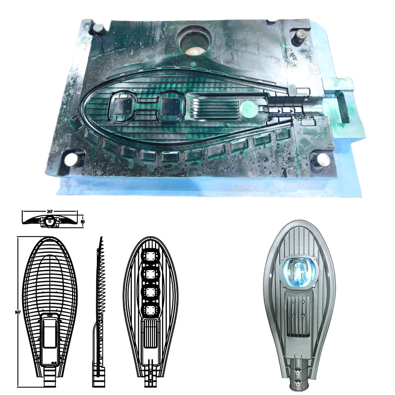
When engineering an aluminum street light die casting mold, complex enclosures and heat sinks present unique challenges. Deep, thin cooling fins require higher draft angles, often exceeding 2° or 3°, to prevent the fins from breaking off inside the tool during ejection. The draft must carefully balance the thermal dissipation needs of the final product with the structural release requirements of the mold. If the fins are too heavily drafted, they become too thick at the base, trapping heat and causing porosity. If they lack draft, they stick in the die.
High-volume consumer goods present a different set of priorities. Designing an aluminum cookware die casting mold requires a strict focus on how draft angles interact with cosmetic surface finishes. Textured surfaces require an additional 1° to 1.5° of draft per 0.025mm of texture depth. This prevents the abrasive aluminum from dragging across the steel and marring the final cosmetic appearance before the non-stick coatings are applied.
Automotive components, such as transmission housings, require a hybrid approach. These parts often feature deep internal cavities for gears and shafts, alongside external mounting flanges. The internal cavities require heavy draft to release from the massive steel cores, but the mounting flanges often require secondary machining to achieve perfect flatness and perpendicularity. In these cases, draft is added to provide extra material (machining allowance) that is later milled away.
Telecommunications equipment, like 5G base station housings, relies heavily on draft to manage weight and thermal performance. These massive parts feature hundreds of cooling fins and mounting bosses. A failure to apply proper draft to even a single boss can cause the entire casting to warp during ejection, rendering the part useless. Tooling engineers spend weeks optimizing the draft on these models to ensure a balanced ejection force across the entire surface area.
Proper draft directly eliminates drag marks and scuffing. This is particularly critical at the gate, where molten metal velocity and thermal load are at their highest. The gate area experiences the most severe wear in the entire die. If strict perpendicularity is required near the gate, engineers must design draft into features that will be CNC machined away post-casting.
Draft alone is insufficient without proper internal fillets. Sharp right angles combined with minimal draft create severe stress concentrations. These concentrations lead to part cracking and physical mold damage during ejection. Generous radii distribute ejection forces evenly across the part geometry, allowing the draft to do its job and break the friction.
Optimal draft angles correlate directly with reduced thermal fatigue and mechanical wear on the mold. By reducing the required ejection force, proper draft extends the life of ejector pins, core pins, and the die base itself. A tool designed with generous draft will run hundreds of thousands of shots with minimal maintenance, lowering overall production downtime and cost per part.
Surface finish requirements dictate draft tolerances heavily. If a part requires a high-gloss polish or a specific powder-coated texture, any drag marks caused by insufficient draft will telegraph through the final finish. The cost of manually polishing out drag marks on raw castings destroys profit margins. Adding an extra 0.5° of draft eliminates this secondary labor entirely.
You must also evaluate how draft affects the weight of the final part. In aerospace or automotive applications where lightweighting is critical, excessive draft adds unnecessary mass to the component. Engineers must calculate the exact minimum draft required for a clean release without adding excess aluminum to the walls. This requires precise mold flow and thermal analysis.
Failing to optimize draft angles introduces significant manufacturing risks that will halt production and require expensive tool modifications.
Risk: Ejection Failures and Part Distortion. Mandate mold flow and thermal solidification analysis during the DFM stage. This identifies hot spots where the part may grip the mold tighter than anticipated, allowing you to increase draft in those specific areas before cutting steel.
Risk: Dimensional Tolerance Creep. Establish clear datum structures on your drawings. Because draft changes the dimension of a feature from top to bottom, explicitly specify whether critical dimensions apply to the root, the tip, or the average of the drafted feature.
Risk: Misalignment Between Design and Manufacturing Capabilities. Require tooling partners to provide a comprehensive DFM report detailing every proposed draft angle deviation from the original CAD model. Review and approve these changes before authorizing tool fabrication.
Risk: Core Pin Breakage. For deep, narrow holes, specify a minimum of 2° draft and ensure the toolmaker uses high-hardness core pins with proper cooling channels to prevent the aluminum from soldering to the pin.
Risk: Cosmetic Defects on Textured Surfaces. Always calculate the required draft based on the specific texture depth callout. Do not rely on standard draft angles if you are applying a heavy sandblast or stipple finish to the cavity.
Incorporating a standard 1° to 2° draft angle is a non-negotiable requirement for reliable, cost-effective aluminum die casting. Deviating from these baselines requires specific justification, advanced tooling techniques, and a willingness to accept higher maintenance costs. When evaluating a die casting partner, prioritize manufacturers who push back on zero-draft designs and provide detailed, feature-by-feature DFM feedback regarding draft, fillets, and ejection strategies.
Audit your current CAD models to ensure compliance with standard draft angle baselines across all internal and external features.
Identify critical-to-function surfaces that require strict perpendicularity and add machining allowances to account for the necessary draft.
Submit your revised models to your tooling partner for a formal thermal and flow evaluation to identify potential ejection hot spots.
Establish clear datum structures on your engineering drawings to account for dimensional shifts caused by the applied draft angles.
A: While 0.5° can sometimes be used for very shallow external cavities, the safe industry standard for most aluminum die casting applications is between 1° and 2°. This baseline accommodates the abrasive nature of aluminum and ensures consistent, clean ejection without damaging the tooling.
A: As molten aluminum cools, it naturally shrinks. It shrinks away from external cavity walls, reducing friction. However, it shrinks tightly onto internal cores. This gripping action requires a larger draft angle (typically 1.5° to 2°) to break the friction and allow the part to eject without galling.
A: Die casting utilizes precision steel molds, allowing for tighter draft control (often 1° to 2°) compared to sand or investment casting, which typically require 1.5° to 3° or more. However, insufficient draft in die casting carries higher risks of metal galling and severe tool wear due to the high-pressure environment.
A: Textured surfaces increase friction during ejection. The general rule of thumb is to add 1° to 1.5° of draft for every 0.001 inches (0.025mm) of texture depth. This prevents the aluminum from dragging against the texture and marring the cosmetic finish.
A: While technically possible for extremely shallow features, zero-degree draft is highly discouraged in commercial reality. It causes high wear on the tooling, increases the risk of galling, slows down cycle times, and almost always requires secondary machining to achieve the final dimensions.
A: The gate experiences the highest molten metal velocity and thermal load, increasing metal-to-mold adhesion. Proper draft angles in these high-velocity zones break the vacuum instantly during ejection, preventing the aluminum from dragging and scuffing against the steel.
A: Insufficient draft leads to a cascade of manufacturing issues. Symptoms include severe galling, drag marks on the part surface, bent or broken ejector pins, warped parts during ejection, and premature wear on the mold cavity.
