
EMAIL:
lh@longhuamachine.com
TELL/whatsapp:
+8619305527239  English English

Views: 0 Author: Site Editor Publish Time: 2026-10-23 Origin: Site


The die casting process turns molten metal into precise parts in six main steps. A clear process overview helps any buyer follow the full journey.
Die preparation
Metal melting
Injection
Cooling
Ejection
Trimming and finishing
Each step relies on a die casting machine, careful parameters, and skilled operators. The casting process shapes every die-cast part, and high-pressure die casting delivers tight tolerances at speed. This guide explains each stage, the equipment involved, common defects, and how to choose a partner. Teams manufacturing die-cast parts value this casting knowledge. A well-run die-casting line protects the mold and produces quality die-cast parts every cycle.
Die casting turns molten metal into precise parts in six steps: die preparation, melting, injection, cooling, ejection, and finishing.
Good mold design controls part shape, quality, and cost; it prevents defects like flow marks and porosity.
Choosing the right alloy and controlling temperature are key for strong, accurate parts.
Injection pressure, speed, and cooling time must be balanced to avoid defects and keep production fast.
A reliable die casting partner with strong quality control ensures parts meet specifications and reduces lead times.
Mold design is a critical step because it determines the shape and features of the final die-cast part. Engineers design the mold with a cover half and an ejector half. The parting line is where these two halves meet. The die is designed so the casting stays in the ejector half and ejector pins push it out. Draft on surfaces parallel to the die opening direction allows easy ejection. Fillets remove sharp edges and corners. Bosses need uniform wall thickness for maximum integrity and strength. Ribs add support without increasing wall thickness. Holes and windows need generous draft to prevent gripping during solidification.
Gate design controls molten metal entry. Poor gate location causes flow marks, cold shuts, and trapped gas. Venting design allows air to escape during injection. Poor venting leads to gas porosity and surface pits. Cooling design governs solidification. Uneven cooling causes shrinkage, warpage, and dimensional drift. Ejector pin position leaves visible marks. Mold precision determines CNC machining allowance and batch consistency.
Operators clean the die before each run. They spray lubricant to aid ejection and protect the die surface. Die lubricants form a protective film that prevents solder and provides smooth release of the casting. Plunger lubricants minimize wear on the plunger tip and sleeve. Soft water is suggested for diluting water-based die lubricants. Water with up to 100 ppm total hardness has been used with no adverse effects.
Preheating the die is essential for quality. The table below shows recommended preheating temperatures.
Component | Recommended Preheating Temperature |
|---|---|
Mold (for aluminum alloys) | Above 180°C |
Feed tube (cold chamber die casting machine) | 315–427°C |
Proper die temperature and lubricant coverage protect the mold and ensure quality die-cast parts every cycle.
Mold design directly affects part quality, cost, and lead time. The parting line location affects polishing, coating, and appearance inspection. Engineers must confirm the parting line before mold design for visible surfaces. Gate design controls molten metal entry. Poor gate location or imbalance causes flow marks, cold shuts, trapped gas, weak areas, and visible defects on cosmetic surfaces. Venting design allows air to escape during injection. Poor venting leads to gas porosity, surface pits, weak areas, and machining problems, especially on sealing or structural faces. Cooling design governs solidification. Uneven cooling causes shrinkage, warpage, deformation, hot spots, dimensional drift, and longer cycle times. Ejector pin position leaves visible marks. Placement on cosmetic areas requires extra polishing, coating, or redesign. Mold precision determines CNC machining allowance and batch consistency. Poor precision leads to unstable stock, shifted holes, sealing face issues, and higher inspection costs.
The die casting process relies on non-ferrous alloys. Aluminum, zinc, and magnesium are the three most common choices. Each metal brings distinct properties to die-cast parts.
Aluminum alloys dominate high-pressure die casting. Alloy 380 offers an excellent balance of mechanical properties and cost-effectiveness. It provides good strength, corrosion resistance, and thermal conductivity. Transmission housings, engine components, and electronics often use this alloy. Alloy 383 delivers better heat resistance and fluidity than 380. It suits thin-walled, complex parts. Alloy 413 provides exceptional pressure tightness for hydraulic cylinders and engine blocks. A360 offers superior corrosion resistance and higher strength than 380. B390 delivers exceptional wear resistance for brake components and automotive pumps.
Alloy | Key Properties | Common Uses |
|---|---|---|
Aluminum Alloy 380 | Excellent balance of mechanical properties and cost-effectiveness; good strength, corrosion resistance, and thermal conductivity; easy to cast and machine | Transmission housings, engine components, furniture frames, electronics |
Aluminum Alloy 383 | Better heat resistance and fluidity than 380; improved corrosion resistance; excellent for thin-walled, complex parts | Complex automotive parts, electrical housings, consumer electronics |
Aluminum Alloy 413 | Exceptional pressure tightness; excellent corrosion resistance; high thermal and electrical conductivity; good castability | Hydraulic cylinders, engine blocks, gear cases |
Aluminum Alloy A360 | Superior corrosion resistance; higher strength than 380; excellent mechanical properties; slightly more difficult to cast | Engine components, transmission housings, industrial equipment |
Aluminum Alloy B390 | Exceptional wear resistance and high hardness; less ductile and more difficult to machine | Engine blocks, brake components, automotive pumps |
Zinc alloys melt at lower temperatures. They reduce energy use and extend tool life. Magnesium alloys offer the lowest density among the three.
Melting turns ingot, returns, and scrap into usable molten metal. Gas-fired and electric furnaces both serve this purpose. A melting furnace supplies metal. A holding furnace maintains a controlled reserve near the casting machine. Holding furnaces buffer demand changes and reduce temperature swings.
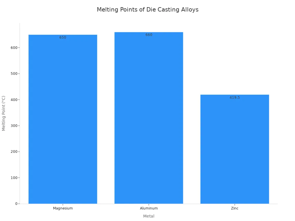
Precise temperature control is essential. The temperature of the molten metal must reach its melting point without overheating. Magnesium melts at 650°C. Aluminum melts at 660°C. Zinc melts at 419.5°C.
After melting, the metal is poured into molds. This step of pouring molten metal into a mold requires preheated dies to prevent thermal shock. The metal then cools and solidifies under controlled conditions. Once cooled, workers remove the cast parts for finishing steps like trimming, deburring, or machining. Proper melting and temperature control directly affect the quality of every die-cast part produced.
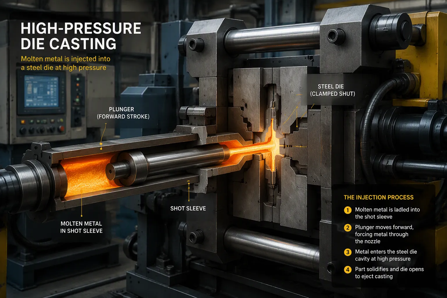
Injection is the core of the high-pressure die-casting process. A piston or plunger forces molten metal into the die cavity at high speed and pressure. This step determines whether the final die-cast part meets specifications or fails.
The die casting machine fills the cavity through a precise sequence. First, a metered amount of molten metal is dosed into the shot sleeve, which is often thermally regulated to minimize deformation. A plunger then drives the melt through the shot sleeve and gating system in two phases.
Slow shot (pre-fill): the plunger advances at lower velocity to control wave formation, limit air entrapment, and position the metal near the gate.
Fast shot (fill): the plunger switches to high velocity, and once the melt accelerates through the gate, the piston speed in this second phase combined with the injection gate design drives the filling of the die cavity.
After filling, intensification pressure is applied to pack the metal as it solidifies, improving dimensional accuracy and reducing variability.
Different machine types handle this process differently. Cold-chamber die casting machines ladle molten metal into a separate shot chamber, then a ram vertically forces the metal into the die. Hot-chamber die casting machines melt metal in a furnace inside the casting machine, and a hydraulic system injects the molten metal directly into the die under high pressure. Cold-chamber machines suit high-melting-temperature alloys such as aluminum, while hot-chamber machines work best with low-melting-point alloys such as zinc, tin, lead, and magnesium.
Injection pressure, injection speed, and cycle time are the three key parameters of the high-pressure die-casting process. Injection pressure drives molten metal into the mold cavity and rapidly fills the part geometry. Typical injection pressures in high-pressure die casting range from 10–175 MPa, or 1,500–25,000 psi.
Method | Cycle Time |
|---|---|
High-Pressure Die Casting | Fast (seconds) |
Low-Pressure Die Casting | Moderate (1–3 minutes) |
Gravity Die Casting | Slower (2–5+ minutes) |
Injection speed controls how fast metal enters the mold. For most applications, the optimum injection speed is about 50 to 300 mm/s. Speeds that are too high can cause surface defects and sink marks because the material may not flow evenly and cools quickly. Speeds that are too low can lead to incomplete mold filling and air pockets.
Holding pressure is the force maintained after injection to compact the mold and compensate for material shrinkage. A correctly set holding pressure prevents warping and ensures stable mold dimensions, typically at 70–80% of the maximum injection pressure. Too high a holding pressure can lead to internal stresses, while too low a holding pressure can impair mold filling.
Cycle time in high-pressure die casting is primarily determined by shot timing, including phase 1 and phase 2 piston speed, the switch-over point, gate velocity, filling time, and holding time. Filling time is the window in which the cavity must be filled before freezing disrupts flow. If too long, defects such as cold shuts or incomplete fill become more likely. Holding time allows pressure to stabilize dimensions and support solidification. If too long, it increases cycle time without improving the part. Faster cycles are achieved by shortening ineffective time rather than pushing every setting to an extreme.
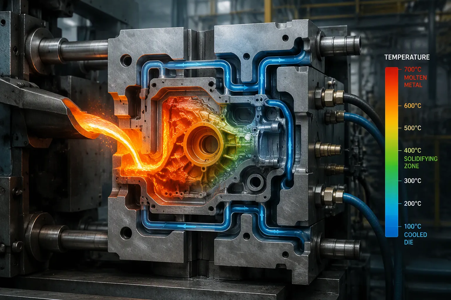
After injection, the molten metal cools and solidifies inside the die to achieve its final geometry. This stage transforms the liquid shot into a rigid die-cast part. Proper cooling and solidification control prevent defects and ensure dimensional accuracy. The process also sets the internal structure of the casting, which affects strength, surface finish, and how well the part performs in service.
Cooling channels inside the die remove heat at a controlled rate. Uniform cooling minimizes differential contraction and internal stresses. This approach reduces warpage by up to 25%. Controlled cooling rate management also reduces internal porosity by up to 30%, because gradual cooling helps trapped gases dissipate more effectively and produces denser castings. Cooling rate optimization for uniform solidification reduces shrinkage defects by up to 20%, since uniform cooling minimizes stress concentrations that lead to hot tearing.
Defect | Cooling-Related Solution | Quantified Effect |
|---|---|---|
Warpage | Uniform cooling via cooling channels | Reduces warpage by up to 25% |
Porosity (surface and internal) | Controlled cooling rate management | Reduces internal porosity by up to 30% |
Shrinkage and hot tearing | Cooling rate optimization for uniform solidification | Reduces shrinkage defects by up to 20% |
Several causes drive shrinkage and porosity in manufacturing die-cast parts. Uneven wall thickness makes thick sections solidify slower than thin ones, creating hot spots. Insufficient feeding leaves no molten metal to compensate for shrinkage during cooling. Poor cooling system design creates inconsistent cooling rates and internal cavities. Improper gating design prevents metal flow from reaching isolated areas before freezing. Solutions include uniform part design, mold cooling optimization with localized cooling channels, feeding design using overflows or risers, and simulation tools that predict shrinkage-prone areas before tooling is manufactured.
Warpage occurs when uneven cooling or residual stresses cause permanent deformation of die casting parts after ejection. This defect is particularly problematic in thin-walled or complex geometry components where differential cooling rates create internal stresses that overcome the material's yield strength. Prevention requires careful attention to cooling system design and ejection timing.
Cooling time and die temperature must stay in balance. Cooling the die quickly boosts production speed, but rapid cooling causes thermal expansion and contraction cycles that lead to heat checking and shorten die lifespan. Using the lowest feasible metal temperature reduces heat stress on the die, since alloys freeze over a range of temperatures and allow some flexibility. Letting the die cool slightly before spraying reduces thermal shock and heat checking. A cooler die surface can still work effectively with die spray.
Lubricant selection also matters. The choice of lubricants and their dilution rate affects surface heat checking. Higher water-to-lubricant ratios may require more mix to apply the necessary release film, which can increase temperature fluctuations at the die surface. Die casting economics depends on maximizing die lifespan while maintaining efficient production rates. The goal is to find the sweet spot where die life cost per cycle plus cycle cost are optimized. This balance keeps the process stable and protects the mold across thousands of cycles.
Once the metal solidifies, the die halves open and the casting must leave the mold. Ejection is the step that frees the solid part from the die cavity. This stage directly affects part quality and cycle time in high-pressure die casting.
Ejector pins are essential mold components designed to push finished parts out of the mold cavity. During ejection, they apply a controlled force at a carefully timed moment so the part is released without damage. Different pin designs—such as standard cylindrical pins, ejector blades for thin walls, and stepped pins for complex shapes—are chosen based on part geometry. The pins are positioned to push on strong areas like ribs or bosses, which helps minimize visible pin marks and preserve the part's appearance and structure.
The ejection sequence follows a precise order. Molten metal is injected under high pressure into the die cavity. The metal solidifies inside the mold. The die halves are opened. Ejector pins are activated and push against the solidified casting. The pushing action breaks the casting free from the die. The finished part is removed, and the die is prepared for the next cycle.
Poorly controlled ejection can cause deformation or damage, especially for thin-walled or geometrically complex castings. Part extraction and handling also add delays. Manual extraction adds 10–20 seconds per cycle, particularly for complex geometries requiring careful manipulation. Automated part extraction mechanisms eliminate bottlenecks in the production cycle. These systems help manufacturers producing die-cast parts maintain consistent output.
Release agents prevent the casting from sticking to the die and protect the part surface during ejection. Common types include waxes, fatty esters, silicones, metallic soaps, and water-based die lubricant (WBD), which has been used in die casting for about 40 years.
Key Property | |
|---|---|
Emulsion Release Agent | Water-based formula after dilution |
Water-Based Release Agent | Used in metal casting and die casting |
Sacrificial Release Agent | Applied for metal casting and die casting |
Boron Nitride (BN) Release Agent | Contains hexagonal boron nitride (h-BN); heat resistance up to 1500°C; handles aluminum alloys, various metals, and high-melting-point glass |
Proper release agent application protects every die-cast part from scratches and sticking. A well-tuned ejection process keeps high-pressure die casting efficient and prepares each die-cast part for deburring and final finishing.
After ejection, the raw casting still carries excess material. Trimming removes flash, runners, and overflows from the part. Flash forms when metal escapes between die halves. Runners are the channels that feed molten metal into the cavity. Overflows capture cold metal and trapped gas. Workers trim these unwanted sections and burrs using trim dies, saws, or hand tools. A trim press often handles this task at high volume. The trimming step directly affects dimensional accuracy and surface quality. Poor trimming leaves sharp edges or damages the part. Proper trimming prepares each casting for the next stage of post-processing.
The trimming process begins as soon as the part leaves the mold. Flash appears along the parting line and requires removal with a trim die or manual tool. Runners and overflows connect to the casting through gates. Operators separate these sections and return the scrap metal to the melting furnace. Deburring follows trimming. This step removes sharp edges, small burrs, and rough spots left by the trim operation. Deburring methods include vibratory finishing, tumbling, and manual filing. Each method suits different part geometries and production volumes. Manufacturing die-cast parts at scale demands efficient trimming, deburring, and inspection workflows. Automated systems speed up these tasks and reduce labor costs.
Finishing goes beyond trimming. Surface treatments modify the part's appearance, corrosion resistance, wear resistance, and coating adhesion. Common options include anodizing, powder coating, painting, electroplating, electrophoresis, PVD, shot blasting, and passivation. Anodizing creates an oxide layer on aluminum surfaces for appearance and protection. Powder coating applies a cured protective coating for colored housings and outdoor components. Painting supports color, gloss, texture, branding, and protection. Electroplating provides a metallic finish and corrosion-related performance. Shot blasting removes scale, adjusts texture, and prepares parts for later finishing. The selection depends on the alloy, casting quality, surface condition, and application environment.
Final checks confirm that every finished die-cast product meets specifications. Inspection covers dimensions, surface finish, and functional requirements. Quality control teams measure critical features and document results. This post-machining process may include CNC machining to hit tight tolerances. The entire process, from high-pressure die casting through post-machining to create the finished die-cast product, relies on careful control at every stage. A reliable die-casting partner manages trimming, deburring, and inspection to deliver parts that meet customer needs.
Defects in the die-cast part manufacturing process rarely appear at random. Each one traces back to a specific stage, and each has a known fix. Understanding the cause helps buyers and operators correct the process instead of scrapping parts.
Porosity describes gas pockets or shrinkage voids inside a casting. Trapped air causes gas porosity when venting fails or injection speed runs too high. Shrinkage porosity forms when thick sections cool slower than thin ones and no molten metal remains to feed them. Cold shuts occur when two metal fronts meet but fail to fuse, usually because the metal cooled during a slow fill. Misruns leave sections unfilled when injection pressure or speed is too low.
Prevention ties directly to earlier steps. Proper venting design in the mold lets air escape during injection. Balanced gate design keeps flow uniform. Controlled cooling reduces shrinkage voids. Simulation software predicts these problems before steel is cut, which cuts costly mold trials.
Warping bends a part out of shape after ejection. Uneven cooling or residual stress causes it, and thin-walled parts suffer most. Uniform cooling through well-placed channels reduces warpage by up to 25%. Sink marks appear as shallow depressions on thick sections where material shrinks away from the surface. Correct holding pressure and uniform wall thickness prevent them. Flash is excess metal squeezed out along the parting line, and it signals worn dies, low clamping force, or excessive injection pressure.
Defect | Typical Cause | Prevention Step |
|---|---|---|
Porosity | Trapped gas or poor feeding | Venting, controlled cooling |
Cold shuts | Slow fill, cooled metal | Higher injection speed |
Misruns | Low pressure or speed | Injection parameter tuning |
Warping | Uneven cooling | Uniform cooling channels |
Sink marks | Thick sections, low packing | Holding pressure, wall design |
Flash | Die wear, low clamp force | Die maintenance, clamping |
These defects raise cost and delay delivery. A disciplined quality control routine catches them early. Trimming and deburring remove flash and sharp edges, but prevention at the injection and cooling stages saves far more than rework. Reliable high-pressure die casting depends on controlling every variable from melting through final inspection.
A reliable partner brings proven experience across every stage of the die casting process. The right supplier understands engineering drawings and recommends an appropriate manufacturing method for each project. They maintain dimensional consistency from one production run to the next. Production volume matters too. A capable partner scales output without sacrificing part quality.
Equipment and quality control separate strong suppliers from weak ones. A modern die casting machine and well-maintained molds protect tolerances across thousands of cycles. The supplier should provide proper inspection and quality documentation for every batch. Finishing capabilities also count. Trimming, deburring, and post-processing belong inside the manufacturing solution, not outside it. A partner who treats these steps as an afterthought creates delays and defects. Strong suppliers also communicate clearly when technical issues arise and support production after the first approved sample.
Buyers should ask direct questions before signing a contract. Clear answers reveal whether a supplier can carry a component through its full manufacturing journey.
Can the supplier understand the engineering drawing?
Can the supplier recommend an appropriate manufacturing process?
Can the supplier maintain dimensional consistency?
Can the supplier handle the required production volume?
Can the supplier provide proper inspection and quality documentation?
Can the supplier communicate clearly when there is a technical issue?
Can the supplier support production after the first approved sample?
A strong partner improves design decisions before production begins. They address tooling considerations early, which reduces unnecessary changes and interruptions. They hold specifications and repeatability steady across runs. They also plan finishing and secondary operations as part of the whole solution. Reliability, communication, and responsiveness matter as much as technical skill.
High-pressure die casting rewards this discipline. A dependable partner prevents defects before they happen and controls every step, from the first mold design to the final deburring pass. That control protects die-cast parts, shortens lead times, and keeps casting costs predictable. Buyers who vet suppliers carefully receive die-cast parts that meet specifications on the first delivery.
The die casting process moves through six steps: die preparation, metal melting, injection, cooling, ejection, and trimming and finishing. This process overview shows how each stage shapes die-cast parts. Every step affects quality, cost, and lead time for these die-cast parts. Each process decision ripples through the entire casting. A reliable partner brings expertise in high-pressure die casting. They prevent defects before they happen. Their team controls the casting process from the first mold design through deburring. High-pressure die casting demands this discipline. The process protects die-cast parts and shortens lead times for every casting. High-pressure die casting rewards careful planning. Readers should contact a trusted die casting company for their next project.
Cycle time depends on the alloy and part geometry. High-pressure die casting runs in seconds per shot. Low-pressure die casting takes one to three minutes. Gravity die casting needs two to five minutes or more. Trimming, deburring, and inspection add time after ejection.
Trapped air or poor feeding creates porosity. Gas porosity forms when venting fails or injection speed runs too high. Shrinkage porosity appears when thick sections cool slower than thin ones. Proper venting, balanced gate design, and controlled cooling prevent both types.
Mold design sets the shape, features, and tolerances of every casting. Gate location controls metal flow. Venting releases trapped air. Cooling channels govern solidification. Ejector pin placement affects surface appearance. Engineers confirm the parting line before cutting steel.
Aluminum, zinc, and magnesium alloys dominate the process. Aluminum alloy 380 offers a strong balance of properties and cost. Zinc melts at lower temperatures and extends tool life. Magnesium delivers the lowest density. Cold-chamber machines suit aluminum, while hot-chamber machines handle zinc.
Prevention starts at mold design and continues through every stage. Simulation software predicts shrinkage-prone areas before tooling is cut. Uniform cooling reduces warpage. Correct holding pressure stops sink marks. A disciplined quality routine catches problems early and protects die-cast parts.
